|
|
|
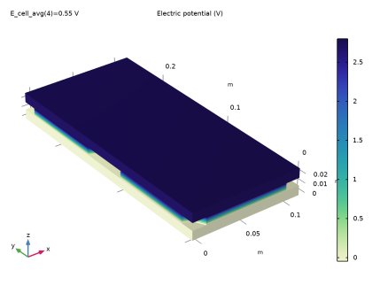
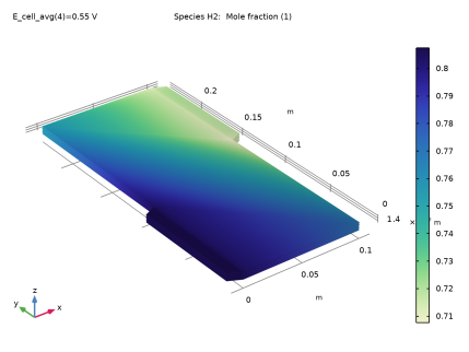
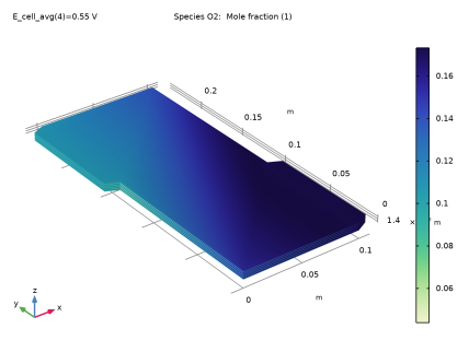
|
1
|
|
2
|
In the Select Physics tree, select Electrochemistry > Hydrogen Fuel Cells > Proton Exchange Membrane (fc).
|
|
3
|
Click Add.
|
|
4
|
In the Select Physics tree, select Fluid Flow > Porous Media and Subsurface Flow > Darcy’s Law (dl).
|
|
5
|
Click Add.
|
|
6
|
In the Select Physics tree, select Heat Transfer > Porous Media > Heat Transfer in Porous Media (ht).
|
|
7
|
Click Add.
|
|
8
|
Click
 Study. Study. |
|
9
|
In the Select Study tree, select Preset Studies for Selected Physics Interfaces > Hydrogen Fuel Cell > Stationary with Initialization.
|
|
10
|
Click
 Done. Done. |
|
1
|
|
2
|
Browse to the model’s Application Libraries folder and double-click the file stack_cooling_geom_sequence.mph.
|
|
3
|
|
4
|
|
5
|
|
6
|
|
7
|
Clear the Automatic detection of small details checkbox.
|
|
8
|
|
9
|
|
1
|
|
2
|
|
1
|
|
2
|
|
3
|
|
4
|
Browse to the model’s Application Libraries folder and double-click the file stack_cooling_physics_parameters.txt.
|
|
1
|
|
2
|
Go to the Add Material window.
|
|
3
|
|
4
|
Right-click and choose Add to Component 1 (comp1).
|
|
5
|
|
6
|
Right-click and choose Add to Component 1 (comp1).
|
|
7
|
In the tree, select Fuel Cell and Electrolyzer > Polymer Electrolytes > Nafion®, EW 1100, Vapor Equilibrated, Protonated.
|
|
8
|
Right-click and choose Add to Component 1 (comp1).
|
|
9
|
|
1
|
|
2
|
|
1
|
|
2
|
|
3
|
|
1
|
|
2
|
|
3
|
|
1
|
|
2
|
|
3
|
Find the Transport mechanisms subsection. Select the Use Darcy’s Law for momentum transport checkbox.
|
|
4
|
|
5
|
Click to expand the Electrolyte and Membrane Transport section. Select the Electroosmotic water drag checkbox.
|
|
1
|
|
2
|
|
3
|
|
1
|
|
2
|
|
3
|
|
1
|
|
2
|
In the Settings window for Water Absorption-Desorption, H2 Side, locate the Absorption–Desorption Condition section.
|
|
3
|
|
1
|
|
2
|
In the Settings window for Water Absorption-Desorption, O2 Side, locate the Absorption–Desorption Condition section.
|
|
3
|
|
1
|
|
2
|
|
3
|
|
4
|
|
5
|
|
6
|
|
1
|
|
2
|
|
3
|
|
4
|
|
5
|
|
6
|
|
1
|
|
2
|
In the Settings window for H2 Gas Diffusion Layer, type H2 Gas Diffusion Layer 2 (manifolds) in the Label text field.
|
|
3
|
|
4
|
|
5
|
|
6
|
|
1
|
|
2
|
In the Settings window for O2 Gas Diffusion Layer, type O2 Gas Diffusion Layer 2 (manifolds) in the Label text field.
|
|
3
|
|
4
|
|
5
|
|
6
|
|
1
|
|
2
|
In the Settings window for Current Collector, type Current Collector 1 (end blocks) in the Label text field.
|
|
3
|
Locate the Domain Selection section. From the Selection list, choose Current Collector and Feeder Plates.
|
|
4
|
|
1
|
|
2
|
In the Settings window for Current Collector, type Current Collector (with cooling flow) in the Label text field.
|
|
3
|
Locate the Domain Selection section. From the Selection list, choose Non-Gas Cooling Channels and Manifolds.
|
|
4
|
|
1
|
|
2
|
|
3
|
|
4
|
|
1
|
|
2
|
In the Settings window for Thin H2 Gas Diffusion Electrode Reaction, locate the Electrode Kinetics section.
|
|
3
|
|
4
|
|
1
|
|
2
|
|
3
|
|
4
|
|
1
|
|
2
|
In the Settings window for Thin O2 Gas Diffusion Electrode Reaction, locate the Electrode Kinetics section.
|
|
3
|
|
4
|
|
5
|
|
1
|
|
2
|
In the Settings window for H2 Gas Diffusion Layer, type H2 Gas Diffusion Layer 3 (x-directed channels) in the Label text field.
|
|
3
|
Locate the Domain Selection section. From the Selection list, choose Hydrogen Gas Channels, x-directed.
|
|
4
|
|
5
|
|
6
|
From the list, choose Diagonal.
|
|
7
|
|
1
|
|
2
|
In the Settings window for H2 Gas Diffusion Layer, type H2 Gas Diffusion Layer 4 (y-directed channels) in the Label text field.
|
|
3
|
Locate the Domain Selection section. From the Selection list, choose Hydrogen Gas Channels, y-directed.
|
|
4
|
|
5
|
|
6
|
From the list, choose Diagonal.
|
|
7
|
|
1
|
|
2
|
In the Settings window for O2 Gas Diffusion Layer, type O2 Gas Diffusion Layer 3 (x-directed channels) in the Label text field.
|
|
3
|
Locate the Domain Selection section. From the Selection list, choose Oxygen Gas Channels, x-directed.
|
|
4
|
|
5
|
|
6
|
From the list, choose Diagonal.
|
|
7
|
|
1
|
|
2
|
In the Settings window for O2 Gas Diffusion Layer, type O2 Gas Diffusion Layer 4 (y-directed channels) in the Label text field.
|
|
3
|
Locate the Domain Selection section. From the Selection list, choose Oxygen Gas Channels, y-directed.
|
|
4
|
|
5
|
|
6
|
From the list, choose Diagonal.
|
|
7
|
|
1
|
|
2
|
|
3
|
|
1
|
|
2
|
|
3
|
|
4
|
|
1
|
In the Model Builder window, under Component 1 (comp1) > Hydrogen Fuel Cell (fc) > H2 Gas Phase 1 click Initial Values 1.
|
|
2
|
|
3
|
|
4
|
|
5
|
|
6
|
|
1
|
|
2
|
|
3
|
|
4
|
Locate the Inlet Flow Type section. From the Inlet flow type list, choose Mixture composition constraint.
|
|
1
|
|
2
|
|
3
|
|
1
|
In the Model Builder window, under Component 1 (comp1) > Hydrogen Fuel Cell (fc) > O2 Gas Phase 1 click Initial Values 1.
|
|
2
|
|
3
|
|
4
|
|
5
|
|
6
|
|
1
|
|
2
|
|
3
|
|
4
|
Locate the Inlet Flow Type section. From the Inlet flow type list, choose Mixture composition constraint.
|
|
1
|
|
2
|
|
3
|
|
4
|
|
5
|
In the Show More Options dialog, in the tree, select the checkbox for the node Physics > Stabilization.
|
|
6
|
Click OK.
|
|
7
|
|
8
|
In the Settings window for Hydrogen Fuel Cell, click to expand the Consistent Stabilization section.
|
|
9
|
|
10
|
|
1
|
|
2
|
|
3
|
|
4
|
|
1
|
In the Model Builder window, under Component 1 (comp1) > Darcy’s Law (dl) > Porous Medium 1 click Porous Matrix 1.
|
|
2
|
|
3
|
|
4
|
|
1
|
|
2
|
|
3
|
|
4
|
|
1
|
|
2
|
|
3
|
|
4
|
|
5
|
|
1
|
|
2
|
|
3
|
|
4
|
Locate the Thermodynamics, Solid section. From the ρ list, choose User defined. From the Cp list, choose User defined.
|
|
1
|
|
2
|
|
3
|
|
4
|
Locate the Heat Conduction, Solid section. From the k list, choose User defined. The thermal conductivity of the gas diffusion layers is anisotropic, featuring a higher conductivity in the in-plane direction.
|
|
5
|
From the list, choose Diagonal.
|
|
6
|
Specify the k matrix as
|
|
7
|
Locate the Thermodynamics, Solid section. From the ρ list, choose User defined. From the Cp list, choose User defined.
|
|
1
|
|
2
|
|
3
|
Locate the Domain Selection section. From the Selection list, choose Current Collector and Feeder Plates.
|
|
1
|
|
2
|
|
3
|
|
4
|
Locate the Heat Conduction, Solid section. From the k list, choose User defined. In the associated text field, type kappa_BPP_eff.
|
|
5
|
Locate the Thermodynamics, Solid section. From the ρ list, choose User defined. From the Cp list, choose User defined.
|
|
1
|
|
2
|
|
3
|
|
1
|
|
2
|
|
3
|
|
4
|
Locate the Thermodynamics, Porous Matrix section. From the ρb list, choose User defined. Locate the Heat Conduction, Porous Matrix section. From the kb list, choose User defined. In the associated text field, type kappa_BPP_eff.
|
|
5
|
|
1
|
|
2
|
|
3
|
|
4
|
|
1
|
|
2
|
|
3
|
|
1
|
|
2
|
|
3
|
|
4
|
|
1
|
|
2
|
|
3
|
|
4
|
|
5
|
|
6
|
Locate the Element Size Parameters section.
|
|
7
|
|
1
|
|
2
|
|
3
|
|
4
|
|
5
|
Click to expand the Source Faces section. From the Selection list, choose Hydrogen Gas Diffusion Electrodes.
|
|
6
|
Click to expand the Destination Faces section. From the Selection list, choose Oxygen Gas Diffusion Electrodes.
|
|
7
|
|
1
|
|
2
|
|
3
|
|
1
|
|
2
|
|
3
|
|
4
|
Click
 Build All. Build All. |
|
1
|
|
2
|
|
3
|
|
4
|
|
5
|
|
1
|
|
2
|
|
3
|
|
1
|
|
2
|
|
3
|
|
4
|
|
1
|
|
2
|
|
1
|
|
2
|
|
3
|
|
4
|
|
1
|
|
2
|
|
1
|
|
2
|
|
3
|
|
4
|
|
1
|
|
2
|
|
3
|
|
4
|
|
1
|
|
2
|
|
3
|
|
4
|
|
5
|
|
6
|
|
1
|
In the Study toolbar, click
 More Study Steps and choose Other > Current Distribution Initialization. More Study Steps and choose Other > Current Distribution Initialization. |
|
2
|
|
3
|
|
4
|
|
1
|
|
2
|
|
3
|
In the Solve for column of the table, under Component 1 (comp1), select the checkbox for Hydrogen Fuel Cell (fc).
|
|
4
|
In the Solve for column of the table, under Component 1 (comp1), clear the checkboxes for Darcy’s Law (dl) and Heat Transfer in Porous Media (ht).
|
|
1
|
|
2
|
|
3
|
In the Solve for column of the table, under Component 1 (comp1), clear the checkbox for Hydrogen Fuel Cell (fc).
|
|
4
|
In the Solve for column of the table, under Component 1 (comp1), select the checkbox for Darcy’s Law (dl).
|
|
5
|
In the Solve for column of the table, under Component 1 (comp1), clear the checkbox for Heat Transfer in Porous Media (ht).
|
|
1
|
|
2
|
|
3
|
In the Solve for column of the table, under Component 1 (comp1), select the checkbox for Hydrogen Fuel Cell (fc).
|
|
4
|
In the Solve for column of the table, under Component 1 (comp1), clear the checkbox for Darcy’s Law (dl).
|
|
5
|
In the Solve for column of the table, under Component 1 (comp1), select the checkbox for Heat Transfer in Porous Media (ht).
|
|
6
|
|
7
|
Click
 Add. Add. |
|
10
|
Click
 Range. Range. |
|
11
|
|
12
|
|
13
|
|
14
|
Click Replace.
|
|
1
|
|
2
|
|
3
|
|
4
|
|
5
|
In the Model Builder window, expand the Study 1 > Solver Configurations > Solution 1 (sol1) > Dependent Variables 3 node, then click Chemical Potential (comp1.fc.mu0).
|
|
6
|
|
7
|
Clear the Solve for this field checkbox.
|
|
8
|
In the Model Builder window, under Study 1 > Solver Configurations > Solution 1 (sol1) > Dependent Variables 3 click Electrolyte Potential (comp1.fc.phil).
|
|
9
|
|
10
|
Clear the Solve for this field checkbox.
|
|
11
|
In the Model Builder window, under Study 1 > Solver Configurations > Solution 1 (sol1) > Dependent Variables 3 click Electric Potential (comp1.fc.phis).
|
|
12
|
|
13
|
Clear the Solve for this field checkbox.
|
|
14
|
In the Model Builder window, under Study 1 > Solver Configurations > Solution 1 (sol1) > Dependent Variables 3 click Mass Fraction (comp1.fc.wH2O_H2).
|
|
15
|
|
16
|
Clear the Solve for this field checkbox.
|
|
17
|
In the Model Builder window, under Study 1 > Solver Configurations > Solution 1 (sol1) > Dependent Variables 3 click Mass Fraction (comp1.fc.wH2O_O2).
|
|
18
|
|
19
|
Clear the Solve for this field checkbox.
|
|
20
|
In the Model Builder window, under Study 1 > Solver Configurations > Solution 1 (sol1) > Dependent Variables 3 click Mass Fraction (comp1.fc.wN2_O2).
|
|
21
|
|
22
|
Clear the Solve for this field checkbox.
|
|
23
|
|
1
|
|
2
|
|
3
|
Click
 Add Physical Quantity. Add Physical Quantity. |
|
4
|
|
5
|
Click OK.
|
|
6
|
|
8
|
|
9
|
Click
 Apply. Apply. |
|
1
|
|
1
|
In the Model Builder window, under Results > Electrode Potential with Respect to Ground (fc), Ctrl-click to select Multislice 1 and Arrow Volume 1.
|
|
2
|
Right-click and choose Disable.
|
|
1
|
|
2
|
|
3
|
Clear the Plot dataset edges checkbox.
|
|
1
|
|
2
|
In the Settings window for Surface, click Replace Expression in the upper-right corner of the Expression section. From the menu, choose Component 1 (comp1) > Hydrogen Fuel Cell > fc.phis - Electric potential - V.
|
|
3
|
|
4
|
|
1
|
|
2
|
|
3
|
Clear the Plot dataset edges checkbox.
|
|
1
|
|
2
|
|
3
|
|
4
|
|
1
|
|
2
|
|
3
|
Clear the Plot dataset edges checkbox.
|
|
1
|
|
2
|
|
3
|
|
4
|
|
1
|
|
2
|
|
1
|
|
2
|
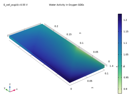
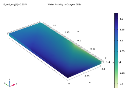
In the Settings window for 3D Plot Group, type Water Activity in Oxygen GDEs in the Label text field.
|
|
3
|
|
1
|
|
2
|
In the Settings window for Surface, click Replace Expression in the upper-right corner of the Expression section. From the menu, choose Component 1 (comp1) > Hydrogen Fuel Cell > fc.aw - Water activity (relative humidity) - 1.
|
|
3
|
|
1
|
|
2
|
|
3
|
|
1
|
|
2
|
|
3
|
Clear the Plot dataset edges checkbox.
|
|
4
|
|
1
|
|
2
|
|
3
|
|
1
|
|
2
|
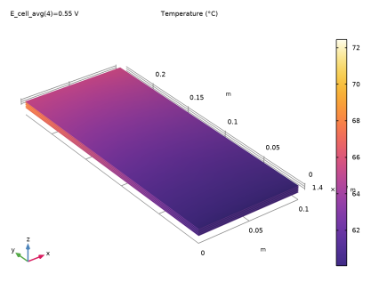
In the Settings window for Surface, click Replace Expression in the upper-right corner of the Expression section. From the menu, choose Component 1 (comp1) > Heat Transfer in Porous Media > Temperature > T - Temperature - K.
|
|
3
|
|
1
|
|
2
|
|
3
|
|
4
|
|
1
|
In the Model Builder window, under Results > Temperature in MEAs right-click Surface 1 and choose Duplicate.
|
|
2
|
|
3
|
|
4
|
|
1
|
|
2
|
|
3
|
|
4
|
|
1
|
|
2
|
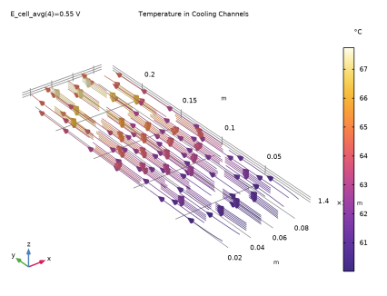
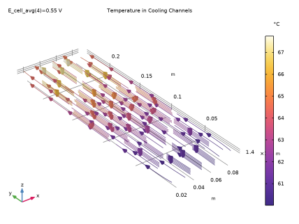
In the Settings window for 3D Plot Group, type Temperature in Cooling Channels in the Label text field.
|
|
3
|
|
4
|
|
5
|
|
1
|
|
2
|
In the Settings window for Streamline Multislice, click Replace Expression in the upper-right corner of the Expression section. From the menu, choose Component 1 (comp1) > Darcy’s Law > Velocity and pressure > dl.u,dl.v,dl.w - Total Darcy velocity field.
|
|
3
|
|
4
|
|
5
|
|
6
|
|
7
|
|
8
|
Locate the Coloring and Style section. Find the Point style subsection. From the Type list, choose Arrow.
|
|
9
|
|
1
|
|
2
|
In the Settings window for Color Expression, click Replace Expression in the upper-right corner of the Expression section. From the menu, choose Component 1 (comp1) > Heat Transfer in Porous Media > Temperature > T - Temperature - K.
|
|
3
|
|
1
|
|
2
|
|
3
|
|
4
|
|
5
|
|
6
|
|
7
|
|
8
|
|
1
|
|
2
|
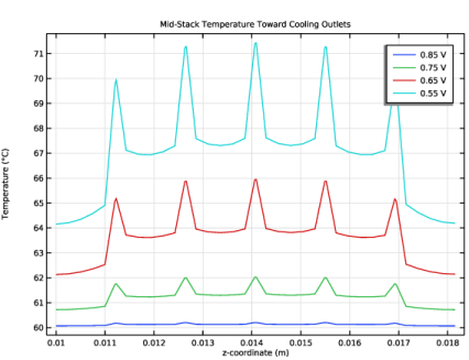
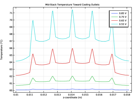
In the Settings window for 1D Plot Group, type Mid-Stack Temperature Toward Cooling Outlets in the Label text field.
|
|
3
|
|
1
|
|
2
|
In the Settings window for Line Graph, click Replace Expression in the upper-right corner of the y-Axis Data section. From the menu, choose Component 1 (comp1) > Heat Transfer in Porous Media > Temperature > T - Temperature - K.
|
|
3
|
|
4
|
|
5
|
|
6
|











 next to