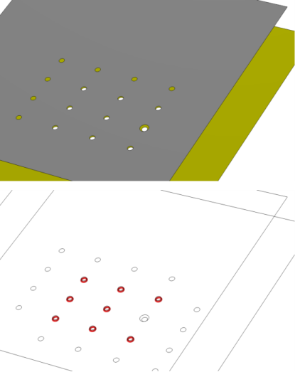
Simplified Modeling of Fasteners
Applicability
The Fasteners node in the Shell interface is intended for approximate modeling of large numbers of fasteners. The most common application is rivets, but with some approximations it is also applicable to, for example, bolts. For spot welds, there is a dedicated feature, described in Modeling Spot Welds.
Since the Shell interface does not represent stresses in the direction normal to she shell, the effects of any prestress of the fasteners is ignored. Forces are transmitted by pure tension and shear in the fastener, while effects of transverse flexibility and loads carried by tangential shear between the plates are ignored. This is a common assumption for rivets. For properly pretensioned bolts, this approach will have the following consequences:
These limitations are, to a large extent, related to the local stress evaluation in the bolt. However, there is also a certain underestimation of the stiffness. This can, to some extent, be mediated by increasing the fastener stiffness.
Modeling Using the Fasteners Node
A fundamental assumption is that the rivet hole is present in the geometry of both the shell boundaries to be joined. The actual connection occurs between two sets of hole edges. As long as the pairs of holes are coincident within some tolerance, all fastener locations can be found automatically. This is the standard way in which you set up a model using the Fasteners node.
A Fasteners node has one or more Hole Selection subnodes. The automatic selection mode is invoked by the choosing Automatic in the Fastener Hole Detection section in such a subnode.
For two holes to be automatically connected by a fastener, the following criteria must be met:
In Figure 2-37, an automatic fastener connection is illustrated. In the upper (gray) plate there are 16 holes. Nine of them has a matching hole in the lower (yellow) plate. One of these holes does, however, have a larger diameter. With default tolerances, eight fasteners will be generated. In the lower part of Figure 2-37, the result template Connected Region Indicator is shown. This plot is an important tool for checking several types of connections.
Figure 2-37: Example of automatic detection of fasteners.
If the conditions for hole matching above are not fulfilled (or cannot be fulfilled by reasonable changes of the tolerance values), you will need to make manual selections for the holes. In that case, you need one Hole Selection subnode for each fastener. Change the setting to Manual in the Fastener Hole Detection section, and make the appropriate edge selections. By using Group by Continuous Tangent, it is easy to select all edges around a hole. In this mode, it is not possible to create more than one fastener per Hole Selection subnode.
You can mix automatic and manual selections under the same Fasteners node.
The automatic search for matching holes can take a significant time if many boundaries are coupled, or there are many mesh elements. If this is a problem, you can do two things:
In the Advanced section in thr settings for Fasteners, change the Search method to Manual, and set a suitable Search distance.
When analyzing riveted structures, it may be necessary to also model contact between connected parallel plates in order to avoid that they penetrate each other. In most cases, a set of fasteners will, however, constrain the plates to such an extent that the advantage of actually including contact in the model is small.
Results
In many cases, you are only interested in the fasteners as a means of obtaining a proper global stiffness of a structure. You can, however access the results in the individual fasteners. There are two result quantities: the axial force and the shear force.
From the Result Templates window, you can add
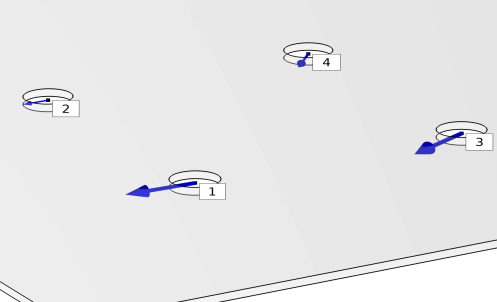
A Fastener Forces plot group, showing the normal and shear forces at each fastener as arrows, and a label showing the identity number of each fastener. Normal forces are plotted as green arrows, and shear forces as blue arrows. The coloring can be affected by a the addition of a Safety subnode.
A Fastener Forces evaluation group, containing a table of the normal and shear forces of all fasteners.
Figure 2-38: Example of a results from a Fastener Forces plot group.
By adding a Safety subnode under Fasteners, you can evaluate the degree of utilization for each fastener.
The damage criterion used is
Here Fn,max and Fs,max, are the critical forces in tension and shear, respectively. The exponents αn and αs are often chosen as 2 for rivets, while other choices are common for bolts, for example α= 2 and α= 3.
If the allowable force are exceeded, that is
then the forces in the Fastener Forces plot group will be colored red.