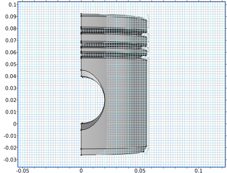
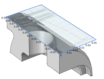
In addition to creating 3D geometries directly using 3D geometric primitives, it is also possible to form 3D geometries based on 2D cross sections (2D geometries) created in work planes or faces in the existing 3D geometry. A work plane is a 2D plane oriented anywhere in the 3D space. Quick options make it easy to create a work plane that is, for example, parallel to any of the main Cartesian planes or to a face or edge in an existing 3D geometry. See
Work Plane for more information about the settings.
It is recommended to unite the work plane objects in 2D, if possible. The objects are united to one single object by default when leaving the Work Plane. Clear the checkbox
Unite objects in the
Settings window of the
Work Plane to keep the separate objects when going to 3D. Keeping separate objects can be useful if modeling domains that will be sliding or moving relative to each other. See
The Form Union/Assembly Node — Uniting the Geometry for more information. If you clear the
Unite objects checkbox, use the
Union operation in the work plane to unite as much of the objects as possible.
It is also possible to add a Form Union/Assembly node from the
Booleans and Partitions (

) menu. The
Form Union/Assembly node has the same effect at the
Unite objects checkbox, but also enables the possibility to add virtual operations to remove short edges, small faces, and similar already in the work plane.
Remove small details from the work plane geometry and prepare it for efficient meshing and analysis by adding operations from the Virtual Operations (

) menu. See
Table 7-14 for a list of available operations. It usually simplifies the workflow by removing unnecessary details early in the process. If there is no
Form Union/Assembly node in the sequence when the virtual operation is added, it will be added automatically. The state of the
Unite objects checkbox of the work plane determines which node is added; a
Form Union node (checkbox selected) or a
Form Assembly node (checkbox cleared).
When using a Work Plane (

) node to define 2D objects in 3D (for example, to extrude into a 3D object), the 3D projection settings enable you to draw on the work plane in 3D. These instructions provide an example. When the
View work plane geometry in 3D checkbox is selected in the
Settings window for the
Plane Geometry node (

) under the
Work Plane node, two additional buttons are available in the
Graphics window — the
Align with Work Plane button (

) and the
Work Plane Clipping button (

). The
Sketch and
Work Plane toolbars are also available for use. The upside of the work plane (defined by the plane’s normal axis) look blue; otherwise, it looks yellow (when using the standard color themes). Those colors help you understand which side of the plane that you are looking at.

