Under a Plane Geometry node (

) you define and create the geometry sequence for a work plane. The
Plane Geometry node also contains some settings for the visualization of the work plane’s geometry.
To open up the Settings window for the
Plane Geometry, click the
Go to Plane Geometry (

) button in the
Settings window for the Work Plane or select the
Plane Geometry node in the
Model Builder. This action typically opens the
The Sketch Toolbar that provides tools for interactive drawing. You also find operations and primitives in the
Work Plane Modal Toolbar.
Select the View work plane geometry in 3D checkbox to create the work plane geometry on the work plane in a 3D view (see
Drawing on a 2D Work Plane in 3D). The default setting is to display the work plane in the
Graphics window as a separate 2D geometry. You can change it by selecting the
View work plane geometry in 3D checkbox on the
Geometry page in the
Preferences window.
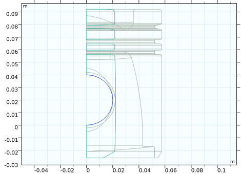
Under In-plane visualization of 3D geometry, specify how to visualize 3D objects in the work plane (as blue curves and points) by selecting one or more of the following checkboxes (all of them are selected by default):
To update the visualization, click the Build Preceding 3D State button to show the effect of the 3D state preceding this work plane. Then, any in-plane visualization of other 3D objects, built using an extrusion from the work plane, for example, that appear below the work plane no longer appears.
Use the Use constraints and dimensions list to enable or disable the use of geometric constraints and dimensions (default:
Off).
If you have selected On, the
Constraint and dimension features to build list determines what constraint and dimension features to include when building the geometry:
