A Combo Box can function as either a combination of a drop-down list box and an editable text field or as a drop-down list box without editing capabilities.
The figure below shows the Settings window for this combo box.
In the Source section, you select a scalar variable that should have its value controlled by the combo box and click
Use as Source. In the
Initial values list of the
Settings window of the combo box, choose a method to define a default value for the combo box. The options are
First allowed value (the default) and
Custom default. For the
Custom default option, enter a default value in the associated field. The default value entered must be one of the allowed values.
In the section for Choice List, you can add choice lists that contribute allowed values to the combo box. The
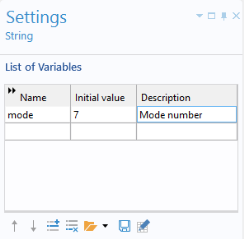
Choice List declaration associated with this example is shown in the figure below.
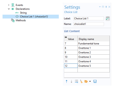
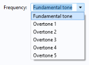
The string variable mode is allowed to have one of these six values:
7,
8,
9,
10,
11, or
12. The text strings in the
Display name column are shown in the combo box.
In the Settings window of the combo box, you can select the
Allow other values checkbox to get a combo box where you can type arbitrary values. These combo boxes can accept any value and are not limited to those defined in the choice lists. In this example, however, only six predefined values are allowed.
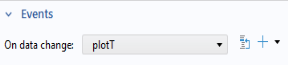
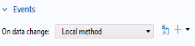
In the Events section, specify a method to run when the value of the combo box, and thereby the string variable used as the source, is changed by the user. In the present case, the value of the variable
mode is changed, and a local method is run, as shown below.
This code links the value of the string mode to the Eigenfrequency setting in the Plot Group
pg1. In this case, the string
svar takes the values
"7",
"8",
"9",
"10",
"11", or
"12".
|
•
|
By default, an Eigenfrequency study for structural mechanical analysis creates a Mode Shape plot group. In this plot group, change the Eigenfrequency from mode 7 to mode 8. In the figure below, this corresponds to changing from 440 Hz to 633.52 Hz in the Settings window for the Mode Shape plot group. 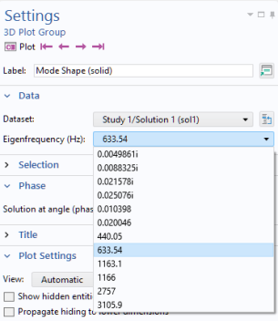
|
Now change the string "8" with the variable
mode to end up with the code listing above. This will be stored in a method, say,
method1. To create the local method associated with the combo box, copy the code from
method1. Then, delete
method1.
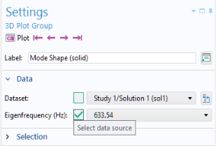
A quicker, but less general way, of using a combo box is to use Data Access in combination with
Editor Tools. For the example used in this section, you start by enabling
Data Access and, in the
Settings window of the
Mode Shape plot group, select the
Eigenfrequency, as shown in the figure below.
In the Editor Tools window, the
Eigenfrequency parameter is visible as
Eigenfrequency (looplevel). To create a combo box, right-click and select
Input.
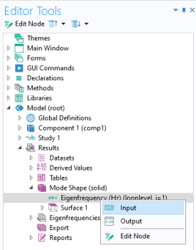
The property name looplevel is used for a solution parameter. If a solution has two or more parameters, then there are two or more loop levels to choose from.
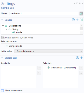
The figure below shows the Settings window of the corresponding combo box.
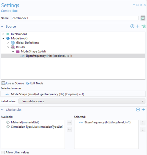
The choice list Eigenfrequency (looplevel) is automatically generated when inserting a combo box using
Editor Tools. Note that a choice list generated in this way is not displayed under the
Declarations node and cannot be modified by the user. For greater flexibility, such as giving names to each parameter or eigenfrequency value, you need to declare the choice list manually, as described in the previous section.
The time parameter list specified in a Time Dependent study step can be used in many places under the
Results node. In an application, the individual time parameters can be accessed in a similar way to what was described in the last section for parameters, by using
Data Access in combination with
Editor Tools.
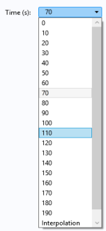
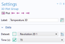
In the Settings window in the figure below,
Data Access has been used to access the
Time parameter list in a temperature plot.
In Editor Tools, a handle to the
Time list is now available, as shown in the figure below.
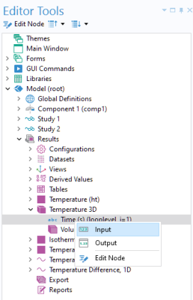
By selecting Input, you can create a combo box using it as
Source, as shown in the figure below.
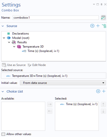
In this case a built-in choice list Time (s) is used to defined the valid options for the time parameters.
Configurations are available in the Model Builder by right-clicking the
Results node and choosing
Configurations from the resulting context menu. Configurations provide centralized control over plot groups, ensuring uniform style and dataset values without adjusting each group individually. Each option applies to multiple plot groups in the model tree and allows simultaneous updates.
|
•
|
Single-Select Solution: Set solution parameters for 2D and 3D plots, such as generating multiple plots with the same time data.
|
|
•
|
Multiselect Solution: Manage 1D plots to show multiple solutions across a parametric sweep or time steps.
|
|
•
|
Graph Plot Style: Customize line width and styles for graph plots (xy-plots) to create consistent visualizations.
|
In addition, the Preferred Units configuration option enables centralized control of default units for a model.
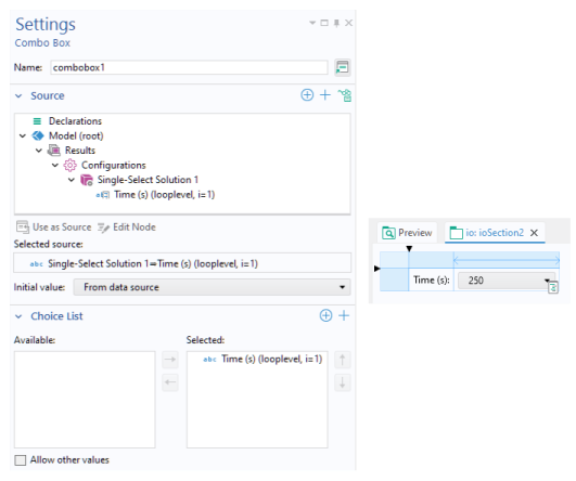
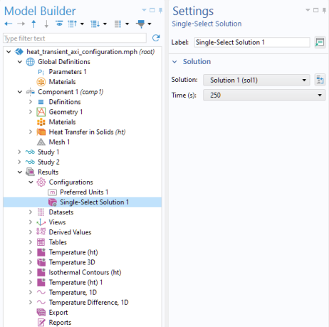
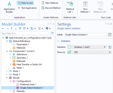
The figure below shows a Single-Select Solution 1 configuration node added to the Axisymmetric Transient Heat Transfer model. The settings window includes the time list which can be accessed via the
Data Access functionality, just as in the example in the previous section.
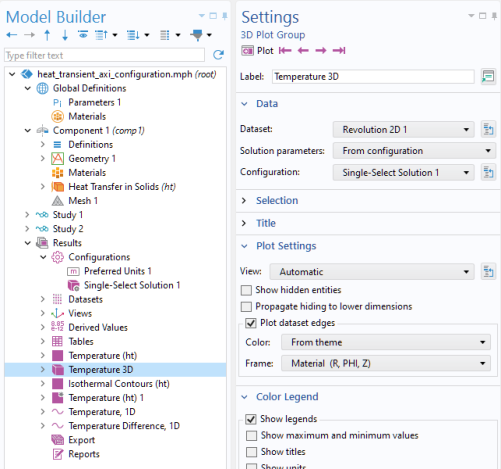
The figure below displays the settings for the Temperature 3D plot group, referencing the
Single-Select Solution 1 configuration. In this way, the time used by the plot group is not locally set but instead determined by the configuration setting.
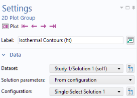
The same reference to the Single-Select Solution 1 configuration can be made from the other plot groups, for example, the
Isothermal Contours plot group as shown below.
Enabling the Data Access functionality makes the
Single-Select Solution 1 time list available from
Editor Tools.
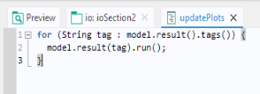
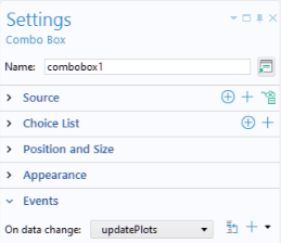
The Events section of the
Combo Box window references a method
updatePlots, as shown in the figure below.
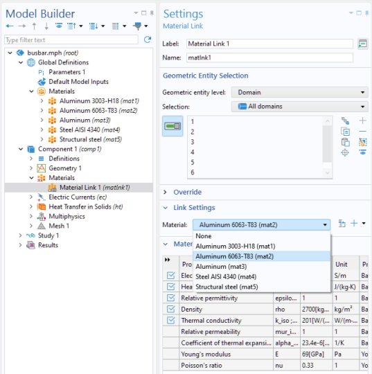
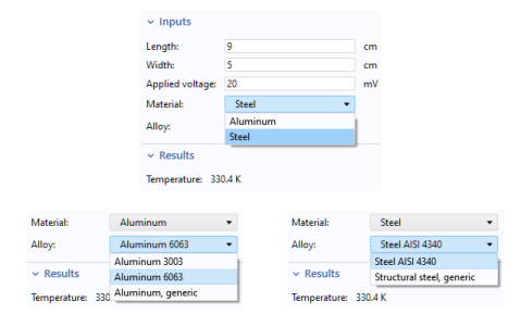
The figure below shows screenshots from an application where the user can choose between two materials, Aluminum or
Steel, using a combo box named
Material. A second combo box called
Alloy shows a list of
Aluminum alloys or
Steel alloys, according to the choice made in the
Material list.
Each material is indexed with a string: mat1,
mat2, …,
mat5. An event listens for changes to the value of the global variable
alloy, where the value is controlled by a combo box. When the value is changed, a method
switchAlloy is run, with one line of code listed below.
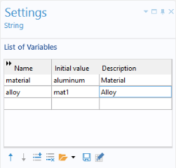
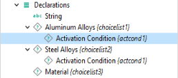
The figure below shows the declaration of two string variables, material and
alloy, which are controlled by the
Material and
Alloy combo boxes, respectively.
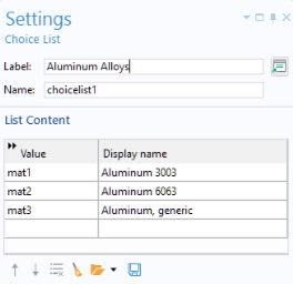
The application utilizes three choice lists: Aluminum Alloys,
Steel Alloys, and
Material.
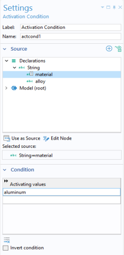
An activation condition is used for the Aluminum Alloys and
Steel Alloys choice lists, as shown in the figure below.
The Settings window for the
Material combo box is shown below.
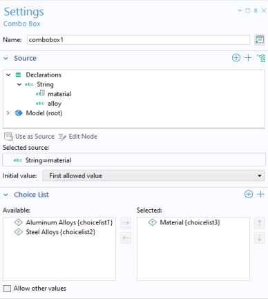
Note that the Material combo box uses the
material string variable as its source. The
Material choice list is used to define a discrete set of allowed values for the
material string variable. The
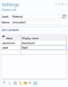
Settings window for the
Material choice list is shown below.
The Settings window for the
Alloy combo box is shown in the figure below.
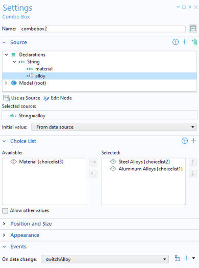
Note that the Alloy combo box uses both the
Aluminum Alloys and the
Steel Alloys choice lists. The choice list for
Aluminum Alloys is shown in the figure below.
The activation condition for the Aluminum Alloys choice list is shown in the figure below.
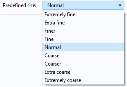
When creating a combo box, you can use the Data Access functionality to reproduce the features of a combo box that exists within the Model Builder. For example, consider an application where a combo box is used to change the element size in a mesh, as in the figure below.
Switch to the Model Builder and select the Mesh node (we assume here that the model has just a single mesh). In the
Settings window of the
Mesh node, select
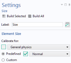
User-controlled mesh (if not already selected). In the settings window for the
Size node, available directly under the
Mesh node, select the option
Predefined. Click
Data Access in the ribbon. This gives access to the combo box for a predefined element size, as shown in the figure below.
|
•
|
Select Combo Box from the Insert Object menu in the ribbon. In the Settings window for the combo box, select the node Predefined size (hauto) in the Source section and then click the Use as Source button.
|
|
•
|
In the Editor Tools window, select the node Predefined size (hauto) under the Mesh > Size node. Then right-click and select Input, as shown in the figure below. 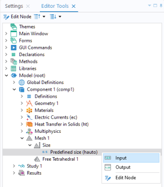
|
The corresponding Settings window for the combo box is shown in the figure below.
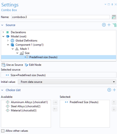
Changing the Initial value to
From data source ensures that the element size setting of the model, in this case
Normal, is used as the default element size in the application. The choice list,
Predefined size (hauto), from the Model Builder is now selected as the choice list for your combo box in the Application Builder. This choice list does not appear as a choice list under the
Declarations node of the application tree because it is being referenced from the Model Builder. Therefore, if you want a list with a more limited set of choices, you cannot edit it. Instead, you have to remove the predefined list as the
Source of your combo box and create a new choice list of your own by declaring it under the
Declarations node. For example, you can create a choice list with three entries, as shown in the figure below.
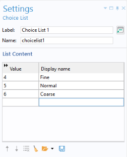
To learn which values are used by the Predefined Size list in the model, use
Record a New Method and change the value from
Normal to
Fine, then to
Coarse, and then back to
Normal. Click
Stop Recording and read the values in the autogenerated code. The
Predefined Size property name is
hauto and the values for
Fine,
Normal, and
Coarse are
4,
5, and
6, respectively, as implied by the automatically generated code shown in the lines below.
The hauto property can also take non-integer values. For more information on mesh options, see
Data Access for Input Fields.
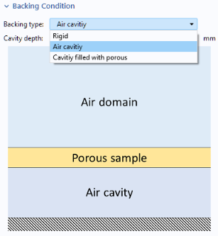
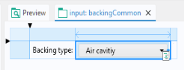
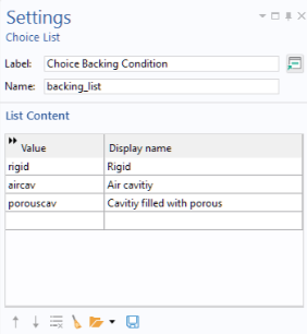
Here, the string variable backingCondition is defined under the
Declarations node in the application tree. The value of this string variable determines the
Backing type physics setting. A combo box allows the app user to modify the value of the string variable, thereby changing the
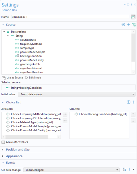
Backing type setting. The allowed values of the combo box is determined by the
Choice List (under
Declarations) named
Choice Backing Condition, as shown below.
Additionally, the combo box is configured with an On data change event, which runs the method
inputChanged whenever the value of the combo box or its associated string variable
backingCondition is updated.
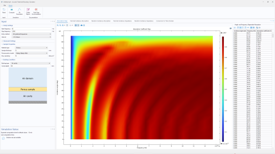
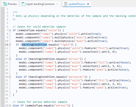
When the computation starts (triggered by the user clicking the Compute button in the app), another method,
updatePhysics, updates the model’s physics settings based on the value of the
backingCondition variable, as shown in the figure below.
If the combo box will be used for the purpose of changing units, then a Unit Set can be used instead of a
Choice List (you still select it in the
Choice List section of the
Settings window of the combo box).