Refine
Use Refine () to refine a mesh by splitting elements by either splitting the longest side of an element, or by inserting centerpoints, as seen in Figure 8-93.
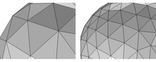
Figure 8-93: A tetrahedral mesh (left) is refined once using the method Regular refinement (right).
To add a Refine () node, select one or several entities in the Graphics window, then choose one of the following:
Right-click in the Graphics window to open The Graphics Context Menu. Select Refine () from the Modifying Operations menu.
Click Modify () on The Mesh Toolbar and select Refine.
Right-click the Mesh node and select Refine () from the Modifying Operations menu.
Then use the following sections to specify the parts of the mesh to refine and the method used to refine the elements:
Domain Selection
Define the domains where you want to refine the mesh. Choose the level of the geometry from the Geometric entity level list:
Choose Entire geometry to refine the entire mesh.
Choose Domain, Boundary (2D and 3D), or Edge (3D only) to specify the domains, boundaries, or edges for which you want to refine the mesh. Choose Manual from the Selection list to select the domains, boundaries, or edges in the Graphics window, choose a named selection to refer to a previously defined selection, or choose All domains, All boundaries, or All edges to select all domains, all boundaries, or all edges, respectively.
Refine Options
Refinement Method
From the Refinement method list, select Regular refinement or Split longest side. The regular refinement method bisects each edge of the element. The result is (with one exception) 2^(element dimension) new elements of the same type. For example, a triangle is split into four triangles; a prism element is split into eight prisms. The pyramid element is the exception: It is split into six pyramids and four tetrahedra. The longest side refinement method bisects the longest edge of each element. This method is generally not suitable for nonsimplex meshes because the refinement destroys the structured nature of such meshes; if you bisect one edge of a regular quad element, you get a triangle and a rather skewed quad element. For 1D elements, these methods are equivalent. For 1D models, this option is excluded.
Number of Refinements
Choose the number of consecutive mesh refinements from the Number of refinements list (the default is one refinement).
Face Representation
Specify which representation to use for the refinement. The setting only affects how mesh vertices are placed on curved faces.
The Face representation setting is only available for 3D meshes that define their own geometric model. A typical example is a mesh imported from file.
Select:
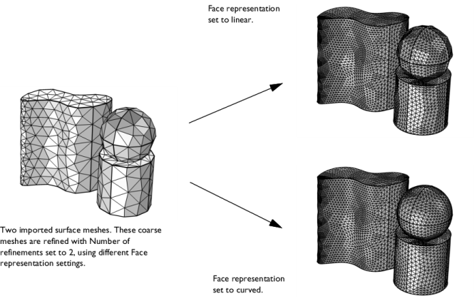
Linear to place new or moved mesh vertices on the input mesh. The resulting mesh will keep the shape of the input mesh to a great extent, as seen in the upper right image in Figure 8-94.
Curved to place new or moved mesh vertices on a curved surface approximation of the input mesh. On curved faces where the mesh has been refined, the resulting mesh will typically be smoother than the input mesh, as seen in the lower right image in Figure 8-94.
Figure 8-94: Two imported surface meshes (left) are refined using the Refine operation. Set the Face representation to Linear to keep the shape of the input mesh (upper right). Use the setting Curved to get a smoother mesh as a curved approximation of the surfaces is used when placing the new mesh vertices. (lower right).
Refine Elements in Box
Check Specify bounding box to refine the mesh only within a box. If you refine the mesh only on certain domains, the mesh is refined only in the intersection between the box and the domains.
Specify the box either by entering the coordinates of the lower-left corner and upper-right corner of the box or click Draw box to interactively specify the box (only available in 2D).
Boundary Layer Meshing — Adding Boundary Layers to an Imported Mesh (2D):
Application Library path COMSOL_Multiphysics/Meshing_Tutorials/valve_boundary_layers_import.
For the Nonlinear Structural Materials Module, see Elastoplastic Analysis of Holed Plate: Application Library path Nonlinear_Structural_Materials_Module/Plasticity/elastoplastic_plate.
For the Electrodeposition Module, see Copper Deposition in a Trench Using the Level Set Method, Application Library path Electrodeposition_Module/Tutorials/cu_trench_deposition_ls.