To use the operation, in the Geometry toolbar, from the
Virtual Operations menu (

), select
Collapse Faces (

). Then enter the properties of the operation using the following sections:
Select the faces that you want to collapse in the Graphics window. They then appear in the
Faces to collapse list. If the geometry sequence includes user-defined selections above the
Collapse Faces node, choose
Manual to select faces, or choose one of the selection nodes from the list next to
Faces to collapse.
Click the Active button to toggle between turning ON and OFF the
Faces to collapse selections.
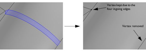
Select the Ignore merged entities check box to ignore the resulting merged edges or vertices (if possible). A vertex will be kept if there are more than two edges connected to the vertex.

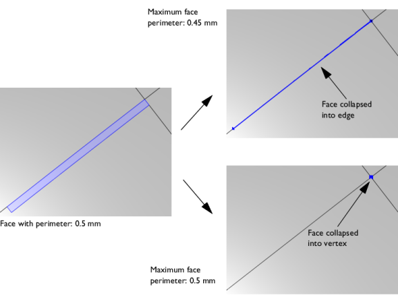
The Collapse to vertex tolerance controls if a sliver face is collapsed into an edge or a vertex. By default, it is set to
Automatic. The default tolerance used is 0.001 times the length of the longest edge of the geometry’s bounding box. For more control, select
Manual to enter a value in the
Maximum face perimeter field that appears. The default value is 0.001. This tolerance is the maximum perimeter of a face to be collapsed into a vertex. If you build the operation with
Automatic and then switch to
Manual, the
Maximum face perimeter field shows the value of the parameter that was used when the operation was built.
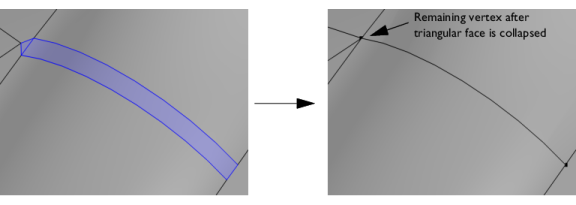
In the case of a face being collapsed into a vertex, it is typically collapsed into the vertex with the most ingoing edges. If that number is the same for all vertices, the face is collapsed to the vertex with the lowest index. With the default Automatic setting a sliver face is more likely to be collapsed into an edge, in which case the tolerance value is set to a value smaller than the face perimeter. For a face that is collapsed to a vertex the tolerance value is larger than the face perimeter.


