You are viewing the documentation for an older COMSOL version. The latest version is
available here.
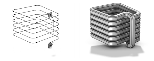
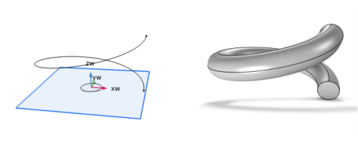
Select Sweep (

) from the
Geometry toolbar to sweep one or several faces, edges, or points along a curve, as seen in
Figure 7-12.
From the Geometric entity level list, choose the level of the entities to sweep:
Boundary,
Edge, or
Point. Then select entities that you want to sweep in the
Graphics window or use the
Selection List window. Click the
Active button to toggle between turning ON and OFF the
Entities to sweep selections. If the geometry sequence includes user-defined selections above the
Sweep node, choose
Manual to select objects or entities, or choose one of the selection nodes from the list next to
Entities to sweep.
When sweeping boundaries, select the Create cross-sectional faces check box (active by default) to make the sweep operation create cross-sectional faces between the sweep sections. Such cross-sectional faces can be useful, for example, for a swept mesh where you want to specify the mesh distribution for each section of the sweep.
Select the Move to spine and match local coordinate systems check box (not active by default) to move the cross section entities to the start of the spine curve. This is supported for cross sections drawn in a
Work Plane and it also matches the origin and z direction of the Work Plane’s coordinate system with the spine curve.
Select the edges you want to sweep along in the Graphics window. More than one edge can be selected, but the selected edges must form a nonclosed connected chain. The edges appear in the
Edges to follow list. Click the
Active button to toggle between turning ON and OFF the
Edges to follow selection.
Select the Manual control of sweep direction check box to change the
Reverse direction setting to manually control in which direction of the spine to sweep the cross section. These check boxes are only available when
Move to spine and match local coordinate systems is not active.
The Smooth edge connections check box is selected by default. Clearing this check box means that transition zones are not added, which can give a better result in cases where the original edges already connect with a continuous tangent.
From the Parameterization list, select one of the following options:
|
•
|
Arc length (the default) to use a parameterization based on the arc length of the spine curve.
|
|
•
|
Normalized arc length to use a similar parameterization but with a normalized arc length (values 0–1).
|
|
•
|
Internal to use the parameterization that is stored in the geometry’s data structures. This option is useful when you want to use the parameterization of a Parametric Curve.
|
In the section Alignment at start select
Make spine perpendicular to entities to sweep to modify the beginning of the spine curve to become perpendicular to the entities selected in the
Cross Section section. Change the
Adjustment parameter length (default 0.1) to modify how far along the spine curve the modification is allowed to propagate. Note that the parameter is dependent on the
Parameterization setting.
In the section Alignment at end select the
Make spine perpendicular to entities check box to modify the end of the spine curve to become perpendicular to a selection of entities. Use this option to connect the end of the sweep with existing geometry with the addition of the option
Add twisting and scaling to match vertices in the
Motion of Cross Section section if the entities do not match up perfectly. With the
Make spine perpendicular to entities check box selected, click the
Active button to toggle between turning ON and OFF the
Entities to match selections, then click to select entities in the Graphics window or use the Selection List. If
Geometric entity level is
Edge or
Point, then the entities must span a plane. Change the
Adjustment parameter length (default 0.1) to modify how far along the spine curve the modification is allowed to propagate. Note that the parameter is dependent on the
Parameterization setting.
Select the Keep input objects check box to use the selected geometry objects for further geometry operations.
With the Keep input objects check box selected, select the
Include all inputs in Form Union/Assembly check box to force the objects in the
Entities to Sweep and
Edges to follow lists to be included in the Form Union/Assembly operation. If the
Include all inputs in Form Union/Assembly check box is not selected, these objects are automatically removed in the Form Union/Assembly operation if the
Entities to sweep list or
Edges to follow list contains all entities in the objects of the selected dimension.
A curve parameter name can be defined in the Parameter name field. Use this parameter in the expressions defining scale factor and twist angle. The parameter is increasing along the chain of edges to follow and is dependent on the
Parameterization setting. This is a local parameter used only for this operation.
Use the Twisting setting to control the twisting of the cross section along the sweep:
|
•
|
Select None (default) to let cross sections for nearby points on the spine curve have as small rotation as possible relative to each other. In other words, the cross sections follow a rotation-minimizing frame. This makes the edges in the sweep direction locally parallel to the spine curve. This option corresponds to the option Twist compensation in earlier versions.
|
|
•
|
Select Follow projection of vector to normal plane to let the orientation of the cross section be governed by a vector that is defined in the text fields x, y, and z that contain expressions that can depend on the parameter. The cross section will follow the projection of this vector to the spine curve’s normal plane. For example, the default vector (0, 0, 1) means that a vector in the initial cross section that is horizontal (in the xy-plane) will stay horizontal in all cross sections.
|
|
•
|
Select Follow curvature vector to let the orientation of the cross section be governed by the spine curve’s curvature vector (also called the normal vector), that is, the vector pointing toward the center of curvature. The local coordinate system formed by the spine curve’s tangent vector, the curvature vector, and the binormal vector is called the Frenet frame. It is not uncommon that a curvature vector varies in a wild way, which creates a bad result.
|
Select the check box Add twisting and scaling to match vertices to select a vertex in the entity to sweep and to match with a vertex at the end. The additional twisting and scaling varies linearly with the parameter. Use this setting together with the setting
Make spine perpendicular to entities in the
Spine Curve section to connect the sweep with existing geometry. Click the
Swap Vertices button (

) to swap the vertices in the two lists.
From the Additional twisting and scaling section, modify the following settings to add extra scaling and twisting to the cross section. These settings are applied after matching vertices, if active.
The Scale factor field controls the size of the cross section, as a function of the parameter.
The Twist angle field contains an additional rotation angle for the cross section, as a function of the parameter.
From the Geometry representation list, select
Spline (the default) to represent the swept object using splines, or
Bézier, to represent the swept object using Bézier curves. With the option
Bézier selected, the spine curve is represented by a sequence of many Bézier curves instead of a few spline curves. In addition to the cross section faces that are created between each pair of edges (if
Create cross-sectional faces is selected), the operation creates cross section edges and vertices corresponding to the swept entities between each pair of adjacent Bézier curves.
The value in the Relative tolerance field is a relative tolerance that controls the accuracy of the geometric representation of the swept object. The geometric representation is an approximation, which is necessary because it is not possible to exactly represent a swept object using NURBS (nonuniform rational basis splines). The default value is 10
−4 (0.01%).
If more than one edge is selected in the Edges to follow list, the
Direction-defining edge controls which edge is used to define the positive sweep direction. The
Direction-defining edge is automatically set when the first edge is added to the
Edges to follow list, so usually it does not have to be changed manually.
Select the Resulting objects selection check box to create predefined selections (for all levels — objects, domains, boundaries, edges, and points — that are applicable) in subsequent nodes in the geometry sequence. To also make all or one of the types of resulting entities (domains, boundaries, edges, and points) that the resulting objects consist of available as selections in all applicable selection lists (in physics and materials settings, for example), choose an option from the
Show in physics (
Show in instances if in a geometry part) list:
All levels,
Domain selection,
Boundary selection,
Edge selection, or
Point selection. The default is
Domain selection, which is suitable for use with materials and physics defined in domains. For use with a boundary condition, for example, choose
Boundary selection. These selections do not appear as separate selection nodes in the model tree. Select
Off to not make any selection available outside of the geometry sequence. From the
Color list, choose a color for highlighting the resulting objects selection. See
Selection Colors.
If you have Named Selections that include entities on the input objects, select the
Propagate selections to resulting objects (selected by default) check box to update the selections to corresponding entities on the output objects, when possible. Clear the check box to not propagate the selection to the resulting objects. This can be useful in combination with selecting the
Keep input objects check box so that the selections refer only to the input objects.
From the Construction geometry list choose
On to make the resulting objects available only in the feature’s geometry sequence. The default option
Inherit means that the resulting objects become construction geometry if all input objects are construction geometry. Choose
Off to never output construction geometry objects. For more information, see
Construction Geometry.