You can create selection nodes under the Component node’s
Definitions node to represent various parts of the geometry and simplify the process of assigning materials, model equations, boundary conditions, and other model properties. These user-defined selections can be reused during modeling and named using descriptive titles — for example,
Tube,
Wall, or
Fluid. Changes to the selection (for example, by adding or removing a boundary) updates all nodes in the Component that use that particular selection. You can also use a named selection to create a certain parts of the geometry that you want to hide from the view (see
Hide for Physics).
Use the buttons listed in Table 6-2 to create, copy, and paste selections. When there is the possibility of overlapping geometric entities, it is recommended that you use
The Selection List Window to ensure the correct part of the geometry is selected.
There are different types of selections: Explicit selections, selections by enclosing part of the geometry by a bounding
Ball,
Box, or
Cylinder, Boolean selections (
Union, Intersection, Difference, and Complement), and selections of
Adjacent geometric entities. To add selection nodes, Click
Selections (

) on the
Definitions toolbar or right-click a
Definitions node and choose from the
Selections options as listed in
Table 6-6.
You can also click Selections (

) on the
Geometry toolbar or right-click a
Geometry node and choose from
Selections options listed in
Table 6-7 for defining selections based on the geometry objects in the geometry sequence. See
Creating Named Selections in the Geometry Sequence. These selections can be used in the geometry sequence as well as when setting up the physics.
For meshes that define their own geometric model, on the Mesh toolbar, click
Selections (

) or right-click a
Mesh node and choose from
Selections options listed in
Table 6-8 for defining selections based on the geometry objects in the geometry sequence. See
Creating Named Selections in the Mesh Sequence. These selections can be used in the meshing sequence as well as when setting up the physics.
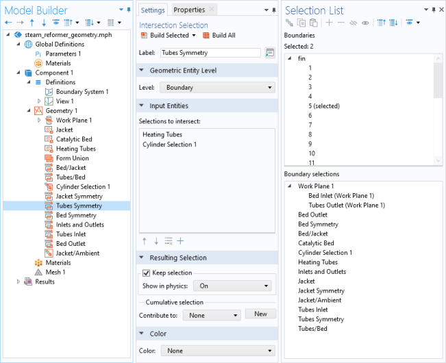
Figure 6-17 uses a COMSOL Multiphysics Application Library example, which includes several user-defined selections.