Wave Heated Discharge Theory
In the Microwave Plasma interface, the electromagnetic waves are computed in the frequency domain and all other variables in the time domain. In order to justify this approach, we start from Maxwell’s equations, which state that:
(6-24)
(6-25)
where is the electric field (V/m), is the magnetic flux density (T), is the magnetic field (A/m), is the plasma current density (A/m2), and is the electrical displacement (C/m2). The tilde is used to denote that the field is varying in time with frequency ω/2π. The plasma current density can be approximated by this expression:
(6-26)
where q is the unit charge (C), ne is the electron density (1/m3), and is the mean electron velocity under the following two assumptions:
1
2
The mean electron velocity on the microwave time scale, , is obtained by assuming a Maxwellian distribution function and taking a first moment of the Boltzmann equation Ref. 2:
(6-27)
where me is the electron mass (kg) and νm is the momentum transfer frequency between the electrons and background gas (1/s). As pointed out in Ref. 1, the equations are linear, so we can take a Fourier transform of the equation system. Taking a Fourier transform of equation Equation 6-27 gives:
where the tilde has been replaced by a bar to reflect the fact that we are now referring to the amplitude of the fields. Multiplying both sides by -ene and re-arranging gives:
or, in simpler form:
where:
(6-28)
Equation 6-24 and Equation 6-25 can be re-arranged by taking the time derivative of Equation 6-25 and substituting in Equation 6-24:
where μ is the permeability, σ is given in equation Equation 6-28 above, and the plasma relative permittivity set to one. The equation could also be recast where the relative permittivity is complex-valued and the plasma conductivity is zero Ref. 3. The convention employed throughout the Plasma Module is that the plasma conductivity is given by equation Equation 6-28 and the plasma relative permittivity is set to 1.
From the theory of the Boltzmann equation in the two-term approximation (see Boltzmann Equation, Two-Term Approximation) the plasma conductivity needs to be modified in order to be coherent with the drift velocity obtained from the Boltzmann equation in the two term approximation.
Solving the above equation with appropriate boundary conditions allows for the power transferred from the electromagnetic fields to the electrons to be calculated:
where J is the total current density (the plasma current plus the displacement current density) and ° denotes the complex conjugate.
Ambipolar Fields
In addition to the equation above, a set of equations are solved in the time domain for the electron density ne, electron energy density nε, plasma potential V, and all ionic and neutral species. These are the same equations solved in the Plasma interface and are given in the Plasma Reactors Theory section.
te and tm mode propagation
In 2D or 2D axisymmetric models, the electromagnetic waves propagate in either the transverse electric (TE) mode or the transverse magnetic (TM) mode. In the TE mode, the electric field is only in the transverse direction and the magnetic field in the direction of propagation. Therefore, COMSOL Multiphysics solves only for the out-of-plane component of the high-frequency electric field. In the TM mode, the magnetic field is in the transverse direction and the electric field only in the direction of propagation, so COMSOL Multiphysics solves only for the in-plane components of the high-frequency electric field.
TE mode
In the TE mode, electrons do not experience any change in the high-frequency electric field during the microwave time scale. This means that the phase coherence between the electrons and electromagnetic waves is only destroyed through collisions with the background gas. The loss of phase coherence between the electrons and high-frequency fields is what results in energy gain for the electrons. Therefore, the momentum collision frequency is simply given by:
where νe is the collision frequency between the electrons and neutrals.
TM mode
The TM mode causes in-plane motion of the electrons on the microwave time scale, so in regions where the high-frequency electric field is significant (the contour where the electron density is equal to the critical density), the time-averaged electric field experienced by the electrons may be nonzero. This destroys the phase coherence between the electrons and the fields, causing the electrons to gain energy. This is an example of a nonlocal kinetic effect, which is difficult to approximate with a fluid model. However, since this effect is similar to collisions with a background gas, the nonlocal effects can be approximated by adding an effective collision frequency to the momentum collision frequency:
where is the effective collision frequency to account for nonlocal effects. This is discussed in more detail in Ref 1, where an effective collision frequency of no more than ω/20 is suggested.
ECR reactors
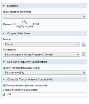
When modeling ECR (electron cyclotron resonance) reactors, another layer of complication is added to the problem. The electron transport properties become tensors and functions of a static magnetic flux density, which can be created using permanent magnets. The plasma conductivity also becomes a full tensor, and a highly nonlinear function of the static magnetic flux density. In addition, it is necessary to consider all three components of the electromagnetic field. Comprehensive details on how to set up and solve a model of an ECR reactor can be found in the Dipolar Microwave Plasma Source model documentation.
Resonance Zone
The above equations are quite straightforward to solve, provided that the plasma frequency is below the angular frequency everywhere in the modeling domain. At a frequency of 2.45 GHz, this corresponds to an electron density of 7.6·1016 1/m3, which is lower than most industrial applications. When the plasma density is equal to this value, the electromagnetic wave transitions from propagating waves to evanescent waves. Applications of microwave plasmas where the electron density is greater than the critical density include:
The resonance zone can be smoothed by activating the Compute tensor plasma conductivity check box in the Plasma Conductivity Coupling multiphysics coupling:
The Doppler broadening parameter, δ, corresponds to the value used for the effective collision frequency via the formula:
Therefore, a value of 20 is a compromise between accuracy and numerical stability as detailed above.
Deposited and Reflected Power
When using the Port boundary condition, the sum of the deposited and reflected power is supplied by default. It is also possible to specify only the deposited power, as shown in the Settings window below:
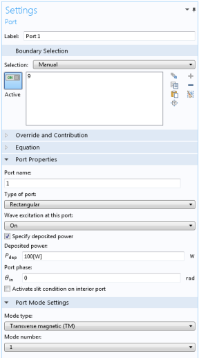
Using this option results in a more stable equation system because the total power transferred to the electrons remains constant. When you use the Port input power option, some of the power is deposited and some is reflected back out of the port, depending on the plasma’s current state. The plasma can go from absorbing a very small amount to a very large amount of power in a very short time period, which can make the problem numerically unstable or lead to the solver taking extremely small time steps. This resonant power absorption mechanism also makes the use of the stationary solver very difficult to use and it is not recommended for such cases.
Modeling Suggestions
The following is a collection of tips and tricks to try to help with convergence and decrease computation time:
Solver Settings
Solver settings play an important role, and COMSOL Multiphysics automatically generates the best solver settings depending on how the model is set up. By default, when the Port input power option is used, the solver settings mentioned below are implemented. The segregated solver is used with two groups:
When the Specify deposited power option in the Port boundary condition is used, the solver suggestion is modified so that there are three groups:
A dependent variable called Pdeposited, which is a differential algebraic equation used to fix the deposited, rather than total power.
In COMSOL Multiphysics the absorption of electromagnetic waves must be realized through a complex-valued electrical conductivity. It is not possible to specify a complex-valued permittivity. The Plasma Conductivity Coupling multiphysics coupling automatically computes the plasma conductivity based on the electron density, collision frequency, and any external DC magnetic flux density that is present.