About Clipping of 3D Model Geometries
The clipping tools are tools in the Graphics window that can be used to look inside of objects in 3D model geometries, in all modeling modes: geometry, physics and materials, mesh, and for result plots. You can use clipping to swiftly hide parts of the geometry that are in the way to, for example, making it easier to do boundary selections inside of complex 3D geometries. These tools are interactive in the Graphics window for 3D models, where you can activate and control the clipping from the Graphics toolbar and directly in the window. Some settings are also available in the View (3D) node’s Settings window. See the sections below for information about the settings for Clip Plane, Clip Box, Clip Sphere, and Clip Cylinder, which you can add from the Graphics toolbar or by right-clicking a 3D View node. Each clip feature is visualized by a frame depicting its geometric shape and a gizmo that lets you interactively position and orientate the clip feature inside of the Graphics window. Several clipping features can be combined and the clipping of each can be inverted to achieve a desired hiding of parts of the 3D geometry. You can cancel any interactive clipping operation by pressing the Escape (Esc) key.
From the Graphics toolbar, you can also choose from the following settings for the active clipping tools, from the Clipping Active () menu:
Click the Clipping Active () button to activate or turn off clipping. You access the settings below from the drop-down menu that you can open next to the Clipping Active button.
Click Clip Primary Hover Effect () to activate of turn off clipping affecting the primary hover effect. Turn it off to see the full entity that you hover on.
Click Clip Contextual Hover Effect () to activate of turn off clipping affecting the contextual hover effect. Turn if off to see all lines from the contextual hover effect.
Click Highlight Intersection () to activate or turn off the highlighting of intersections between the clipping tool and the geometry.
Click Show Frames () to activate or turn off the display of the frames that outline the clipping tools. You can move and resize the clipping tool by clicking and dragging its frame (clip planes cannot be resized). Double-click the frame to move the focus to the corresponding Settings window under the 3D View node.
Click Show Gizmos () to activate or turn off the displays of the gizmos that help you to control the clipping tools. By clicking and moving the gizmo you can move and rotate the clipping tool. Double-click it to move to the corresponding node in the Model Builder to view the settings for the corresponding clipping tool. The gizmo also displays dynamic measurement and coordinate values. The steps for the rotation are determined by a preference setting. Open the Preferences dialog box, and on the Graphics>Interaction>Clipping page, enter a value, in degrees, in the Snap angle field (default value: 5 degrees). You can use a snap angle between 0 and 180 degrees. 0 degrees means that the rotation is continuous without snapping. When dragging the gizmo, rotations are performed around the directions of the main x-, y- and z-axes (the center of rotation is the position of the gizmo), while the translation is done along the gizmo’s own axes (xg, yg, zg). Clicking and dragging one of the gizmo axes leads to translation along that hovered-upon axis, while right-clicking and dragging makes it possible to translate the gizmo on the plane derived from the hovered-upon axis — this option is useful when you quickly want to move the gizmo out of the way for a bit.
Click Show Cross Section () to display or turn off display of the cross section between the clipping tool and the model geometry. The following settings are only available if Show Cross Section is active.
Click Colorize () to display or turn off showing the cross section using a color. See Clipping for more information.
Click Highlight Overlapping Domains () to display or turn off the highlighting of any overlapping domains in a certain color.
Click Make Transparent () to add or turn off transparency for the display of the cross section.
Figure 6-26: A Clip Cylinder tool removes part of the geometry from the view.
Figure 6-27: A Clip Box tool removes parts of the geometry from the view.
Figure 6-28: A Clip Sphere tool with its gizmo at the center of the Clip Sphere.
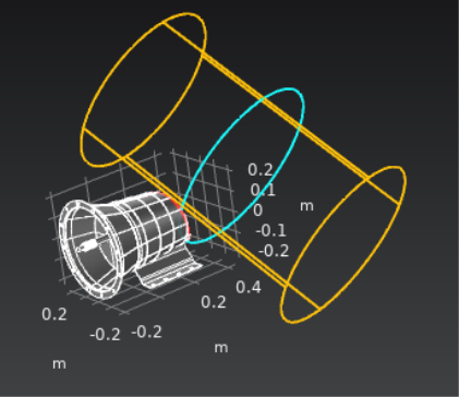
If you add a clipping tool and you cannot see the model geometry, select the Invert clipping check box in the Settings window for the clipping tool. You can then reduce the size of the clipping area to cover only part of the geometry and clear the Invert clipping check box if you want to use the normal clipping mode.