Union
Use a Union node () to unite surface meshes in 3D. The operation introduces mesh edges if mesh elements intersect, thereby intersecting existing mesh elements. It also partitions geometric entities accordingly by, for example, introducing geometry edges where mesh faces intersect, as shown in Figure 8-73. If the surface meshes contain unmeshed domains, the domain information is updated to account for overlap domains.
Figure 8-73: Intersecting surface and edge meshes before and after building the Union operation.
The operation often generates triangles of bad quality close to intersection edges. Use Free Triangular or Free Quad to remesh boundaries. See Remeshing Imported Meshes for more information.
The Union operation partitions existing faces in order to avoid self-intersecting faces. When this happens, an Information node is added with information about additional faces.
To unite meshes:
Select Union () from the Booleans and Partitions menu () on the Mesh ribbon.
Right-click in the Graphics window to open up The Graphics Context Menu and select Union () from the Booleans and Partitions menu.
Right-click the Mesh node and select Union () from the Booleans and Partitions menu.
Enter the properties for the Union node () using the following sections:
Dimension
Define the geometric entities to intersect. From the Geometric entity level list:
Choose Entire geometry (default) to unite all available entities.
Select Domain to unite domains. Choose Manual in the Selection list to select the domains in the Graphics window, choose a named selection to refer to a previously defined selection, or choose All domains to select all domains. Only unmeshed domains can be selected.
Clear the check box Import domain elements in the Settings window of the Import node, or
Add a Delete Entities operation, add the domains to delete, and select the check box Keep as unmeshed domains.
Select Boundary to unite boundaries. Choose Manual in the Selection list to select the boundaries in the Graphics window, choose a named selection to refer to a previously defined selection, or choose All boundaries to select all boundaries.
Choose Edge to unite isolated edges. Choose Manual in the Selection list to select the edge in the Graphics window, choose a named selection to refer to a previously defined selection, or choose All edges to select all edges.
Select Mixed dimensions to specify a mixture of entities to unite.
Geometric Entity Selection
Click the Activate Selection for the entity selections of interest to start adding entities. The selections support unmeshed domains, any boundary, isolated edges, and isolated points.
Cleanup
Intersection of boundary and edge elements can result in short mesh edges, relatively small elements, and elements of poor element quality. To improve the quality of the mesh, cleanup is done by snapping mesh vertices and collapsing short mesh edges. Lower the Repair tolerance to decrease the amount of snapping performed.
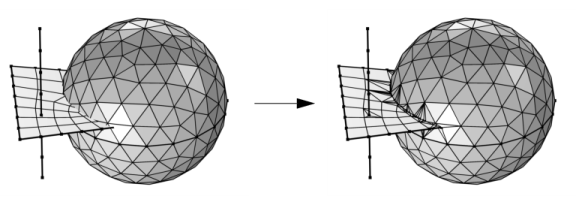
The Union operation can be used to clean up a mesh of very bad quality even if nothing needs to be united. It can, for example, be useful for a mesh imported from a Filter dataset.
Use the Repair tolerance list to control the snapping distance when intersecting faces and for cleanup of the mesh. Choose Relative to enter a value in the Relative tolerance field. This value is relative to the length of the longest side of the mesh bounding box. Select Absolute (the default) to specify a value in the Absolute tolerance field. When the operation is built with either of the settings Automatic or Relative, the values in the Relative tolerance (for Automatic only) and Absolute tolerance fields are automatically updated to correspond to the actually used tolerance. The automatic tolerance is based both on the size of the bounding box and of the average size of mesh elements in the selection.
Select the Cleanup of resulting mesh check box to control if cleanup is performed.