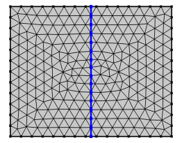
Use an Intersect with Line node (

) to intersect the elements of an imported mesh with a straight line. The selected geometric entities are partitioned by the line. A selection of domains will also lead to a partitioning of adjacent boundaries.
Enter the properties for the Intersect with Line node using the following sections:
Define the geometric entities to intersect. From the Geometric entity level list: Choose
Entire geometry,
Domain, or
Boundary to specify the domains or boundaries to partition with the line or choose a named selection to refer to a previously defined selection. The option
Entire geometry selects all domains and boundaries.
From the Specify list, choose
Coordinates (the default) to specify the positions of a point on the line. Enter values in the corresponding
x and
y edit fields. Alternatively, select
Vertex to select a vertex.
From the Specify list, choose
Direction vector (the default) to specify the direction of the line using a vector. Enter values in the corresponding
x and
y edit fields. Alternatively, select
Second point coordinates or
Second vertex to let the line and its direction be defined by two points. For
Second point coordinates, specify the coordinates in the corresponding
x and
y edit fields. For
Second vertex, select a vertex.
Click the Active button to toggle between turning ON and OFF the vertex selection. To add a vertex to the selection, click on a vertex in the
Graphics window or add one using the
Selection List.
Use the Repair tolerance list to control the snapping distance by choosing
Automatic (the default),
Relative, or
Absolute. Choose
Relative to enter a value in the
Relative tolerance field. This value is relative to the length of the longest side of the mesh bounding box. Select
Absolute to specify a value in the
Absolute tolerance field. When the operation is built with either of the settings
Automatic or
Relative, the values in the
Relative tolerance (for
Automatic only) and
Absolute tolerance fields are automatically updated to be an average of the distances the mesh vertices were actually moved.