Copy Edge
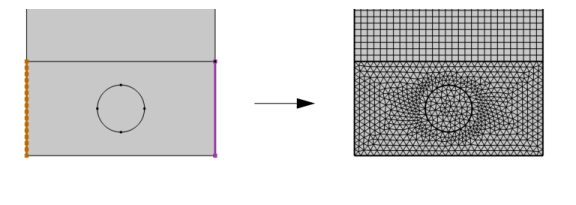
Add a Copy Edge node to 2D () and 3D () models to create identical meshes on edges. A 3D Copy Edge feature can also be used for destination edges of different shapes.
Figure 8-34: Copy the source mesh (yellow) to the destination edge (magenta) with Copy Edge. The image to the right shows the resulting mesh after building the complete mesh. The copy ensures identical meshes on the vertical edges of the domain with an unstructured mesh. The identical mesh is required when applying Periodic conditions on the boundaries.
To copy a mesh between edges, select one or several meshed source edges and unmeshed destination edges, then:
Right-click in the Graphics window, and select Copy Edges from the Copying Operations menu. For more information, see The Graphics Context Menu.
In The Mesh Toolbar, choose Copy Edges from the Copy () menu.
Right-click the Mesh node and choose Copy Edges from the Copying Operations menu.
Then enter the properties for the copy operation using the following sections:
To copy a mesh between edges:
Source and Destination Edges
It is possible to copy a mesh from one or several source edges onto one or several destination edges. The source (or their combination, if many-to-one is used) must be a connected set of exactly the same shape as the corresponding destination, up to a constant scaling factor. More precisely, the distance between any two geometry vertices on the destination is required to be the same, up to a constant scaling factor, as the distance between the corresponding geometry vertices on the source.
Click the Active button to toggle between turning ON and OFF selections. Select the edges to copy the mesh from in the Graphics window.
The source edges must be connected when Single copy (all-to-one) option is specified. In an assembly, an identity pair is not sufficient to connect boundaries across parts. Instead, use the Automatic option or consider forming a union of the parts or splitting the destination boundary (using imprints, for example) so that the mesh copy is a one-to-one copy operation using two or more Copy Edge nodes.
Swap Source and Destination
Click the Swap Source and Destination button () to switch source and destination selections. Edge map is available to be switched, if provided.
Orientation
Select Automatic orientation to let the software determine the orientation of the source mesh on the destination automatically (this is the default), select Same orientation to let the source mesh be copied to the destination according to the direction of the edges, and select Opposite orientation to let the source mesh be copied to the destination in the opposite direction. Use the option Show edge direction arrows in the View node under the Definitions node to view the arrow direction.
Type of Copy
For settings information, see Type of Copy for the Copy operation.
Control Entities
Select the Smooth across removed control entities check box to smooth the transition in element size across removed control entities. You can specify the number of smoothing iterations in the Number of iterations field. In the Maximum element depth to process field you can specify the maximum element depth for the mesh points to be smoothed.
For tutorials using Copy Edge, see:
Voltage Induced in a Coil by a Moving Magnet: Application Library path ACDC_Module/Devices,_Motors_and_Generators/induced_voltage_moving_magnet.
Porous Absorber: Application Library path Acoustics_Module/Building_and_Room_Acoustics/porous_absorber.
Time-Domain Modeling of Dispersive Drude–Lorentz Media: Application Library path RF_Module/Tutorials/drude_lorentz_media.