There are nine predefined sizes to choose from in the Size attribute, ranging from Extremely fine to Extremely coarse. The sizes of the generated mesh elements are determined by absolute mesh size parameters that can be viewed and edited for a user-controlled mesh. The absolute element size parameters depend on the size of the geometry’s bounding box. For example, if half of the geometry is deleted, the bounding box will be smaller. As a result, the maximum element size and minimum element size will be smaller compared to before, even though the same predefined element size has been used. For more information about the different size parameters and how to edit them, see
Element Size Parameters.
Attributes contain size properties defined on a selection. For a user-controlled mesh, it is possible to manually modify the individual size parameters and selection of an attribute. See
The Mesh Node and
Editing and Resetting a Physics-Controlled Sequence for more information about sequence types. You can add a global attribute node directly under the
Mesh node, or add it as a local attribute node under an operation node. Properties defined in a local attribute are only used by the owning operation node while the global attribute nodes define mesh sizes for the whole meshing sequence, either on the entire geometry or on a selection of entities. If more than one attribute is applied on the same selection of entities, the last attribute in the sequence defines the size.
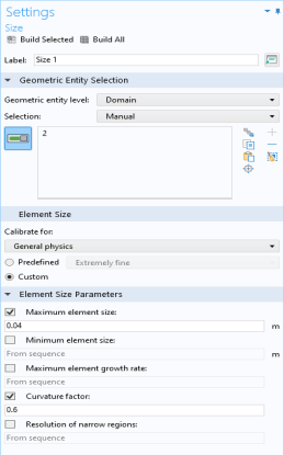
For a local Size attribute, select the Custom option button to modify individual size parameters. If the check box next to a size parameter is not selected, the value is taken from attributes above in the sequence (see
Figure 8-11). To have full control over a size parameter, select its check box.
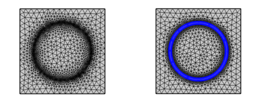
Use a Size Expression attribute to define the size of the mesh elements as function of coordinates, parameters, materials and variables. You can also use global functions, and variables evaluated from solutions in the size expression. Using a coordinate based expression is a useful alternative to creating additional geometric entities in a region of your geometry where you need finer mesh (see
Figure 8-12).