PDF

Heterogeneous Electrode Geometry Generation
Introduction
This example demonstrates how to create a representative 3D geometry of a Nickel-Manganese-Cobalt (NMC) electrode, based on X-ray tomography data. The generated geometry may be used for subsequent heterogeneous electrode modeling.
The X-ray data differentiates between the active NMC particles, and a surrounding mix of electron-conductive carbon additives, binder and ion-conducting electrolyte.
A model method is used to loop through tabulated data on particle volumes and center coordinates.
The geometry generated is used in the Heterogeneous NMC Electrode and Homogenizing a Heterogeneous Electrode Model tutorials in the Battery Design Module Application Library.
Model Definition
Figure 1: Model tree setup. All nodes involved in the geometry generation are highlighted in blue.
Figure 1 indicates the nodes in the model tree used for creating the geometry.
Global Definitions->Geometry Parameters
This node contains parameters related to the generation of the geometry, such as tolerance factors and bounding box.
Results>Tables>Particle Data Table
This table contains the particle center coordinates and the particle volumes.
The data, available as open source, was downloaded from http://dx.doi.org/10.5905/ethz-iis-1. See Ref. 1 for additional information about the data.
Global Definitions>Geometry Parts>Particles
This geometry part contains the individual particle geometric objects (spheres and cylinders) generated from Particle Data Table.
Global Definitions>Generate Geometry From Particle Data Table
This node calls the corresponding model method for generating the Geometry Parts>Particles geometric objects, based on the Particle Data Table.
Each entry in the Particle Data Table generates a Sphere object in Particles, given that the particle is located within the bounding box defined in Geometry Parameters.
Cylinder objects are also added in Geometry Parts>Particles in order to avoid sharp angles between overlapping spheres, or to join spheres together when the mutual distance is lower than the tolerance factor.
The model method also calculates and updates the electrode thickness parameter in Geometry Parameters.
The model method is written in Java, and maybe edited by switching to the Application Builder desktop. Note however that the model method editor is only available in the COMSOL desktop when using Windows. The model method node created in the model is however available and may be executed on all operating systems.
Component 1>Geometry
The final geometry sequence imports the Geometry Parts>Particles, and also includes block geometry objects to define the separator and porous conductive binder domains, based on the settings in Geometry Parameters. Geometry selections are also included in order to facility physics setup.
Results and Discussion
Figure 2 shows the generated model geometry.
Figure 2: Generated model geometry.
Reference
1. M.Ebner, F. Geldmacher , F. Marone , M. Stampanoni, and V. Wood, “X-Ray Tomography of Porous, Transition Metal Oxide Based Lithium Ion Battery Electrodes,” Adv. Energy Mater., vol. 3, pp. 845–850, 2013. See also supporting information at https://onlinelibrary.wiley.com/doi/abs/10.1002/aenm.201200932
Application Library path: Battery_Design_Module/Batteries,_Heterogeneous/nmc_electrode_geometry
Modeling Instructions
From the File menu, choose New.
New
In the New window, click  Blank Model.
Global Definitions
Geometry Parameters
Load some geometry parameters from a text file.
1
In the Model Builder window, under Global Definitions click Parameters 1.
2
In the Settings window for Parameters, type Geometry Parameters in the Label text field.
3
Locate the Parameters section. Click  Load from File.
4
Particles
The particle data is placed in Geometry Parts, which is then imported into the model geometry.
1
In the Model Builder window, right-click Global Definitions and choose Geometry Parts>3D Part.
2
In the Settings window for Part, type Particles in the Label text field.
Create a dummy sphere in the part. This will later be replaced by a collection of objects, generated from a model method.
Sphere 1 (sph1)
1
In the Geometry toolbar, click  Sphere.
2
In the Model Builder window, expand the Particles node, then click Sphere 1 (sph1).
3
In the Settings window for Sphere, locate the Size section.
4
In the Radius text field, type 2e-6.
5
Locate the Position section. In the x text field, type 11e-5.
6
In the y text field, type 7e-5.
7
In the z text field, type 4e-6.
8
Click  Build Selected.
Add Component
In the Home toolbar, click  Add Component and choose 3D.
Geometry 1
Now set up the model geometry sequence, making use of the Particles geometry part.
Particles Part
1
In the Geometry toolbar, click  Parts and choose Particles.
2
In the Settings window for Part Instance, type Particles Part in the Label text field.
3
Click  Build Selected.
Particles
1
In the Geometry toolbar, click  Booleans and Partitions and choose Union.
2
In the Settings window for Union, type Particles in the Label text field.
3
4
Locate the Union section. Clear the Keep interior boundaries check box.
5
Locate the Selections of Resulting Entities section. Select the Resulting objects selection check box.
Block 1 (blk1)
1
In the Geometry toolbar, click  Block.
2
In the Settings window for Block, locate the Size and Shape section.
3
In the Width text field, type xmax-xmin.
4
In the Depth text field, type ymax-ymin.
5
In the Height text field, type L_elec+L_sep.
6
Locate the Position section. In the x text field, type xmin.
7
In the y text field, type ymin.
8
Click  Build Selected.
Partition Objects 1 (par1)
1
In the Geometry toolbar, click  Booleans and Partitions and choose Partition Objects.
2
3
In the Settings window for Partition Objects, locate the Partition Objects section.
4
Find the Tool objects subsection. Click to select the  Activate Selection toggle button.
5
Box Selection 1 (boxsel1)
1
In the Geometry toolbar, click  Selections and choose Box Selection.
2
In the Settings window for Box Selection, locate the Box Limits section.
3
In the x minimum text field, type xmin+geom_tol.
4
In the x maximum text field, type xmax-geom_tol.
5
In the y minimum text field, type ymin+geom_tol.
6
In the y maximum text field, type ymax-geom_tol.
7
Locate the Resulting Selection section. From the Show in physics list, choose Off.
8
Click  Build Selected.
Complement Selection 1 (comsel1)
1
In the Geometry toolbar, click  Selections and choose Complement Selection.
2
In the Settings window for Complement Selection, locate the Input Entities section.
3
4
In the Add dialog box, select Box Selection 1 in the Selections to invert list.
5
6
In the Settings window for Complement Selection, locate the Resulting Selection section.
7
From the Show in physics list, choose Off.
8
Click  Build Selected.
Delete Entities 1 (del1)
1
In the Model Builder window, right-click Geometry 1 and choose Delete Entities.
2
In the Settings window for Delete Entities, locate the Entities or Objects to Delete section.
3
From the Geometric entity level list, choose Domain.
4
From the Selection list, choose Complement Selection 1.
5
Click  Build Selected.
Electrode
1
In the Geometry toolbar, click  Block.
2
In the Settings window for Block, type Electrode in the Label text field.
3
Locate the Size and Shape section. In the Width text field, type xmax-xmin.
4
In the Depth text field, type ymax-ymin.
5
In the Height text field, type L_elec.
6
Locate the Position section. In the x text field, type xmin.
7
In the y text field, type ymin.
8
Click  Build Selected.
Difference 1 (dif1)
1
In the Geometry toolbar, click  Booleans and Partitions and choose Difference.
2
3
In the Settings window for Difference, locate the Difference section.
4
Find the Objects to subtract subsection. Click to select the  Activate Selection toggle button.
5
6
Select the Keep objects to add check box.
7
Select the Keep objects to subtract check box.
8
Click  Build Selected.
Delete Entities 2 (del2)
1
Right-click Geometry 1 and choose Delete Entities.
2
In the Settings window for Delete Entities, locate the Entities or Objects to Delete section.
3
From the Geometric entity level list, choose Object.
4
5
Click  Clear Selection.
6
Separator
1
In the Geometry toolbar, click  Block.
2
In the Settings window for Block, type Separator in the Label text field.
3
Locate the Size and Shape section. In the Width text field, type xmax-xmin.
4
In the Depth text field, type ymax-ymin.
5
In the Height text field, type L_sep.
6
Locate the Position section. In the x text field, type xmin.
7
In the y text field, type ymin.
8
In the z text field, type L_elec.
9
Locate the Selections of Resulting Entities section. Select the Resulting objects selection check box.
10
Click  Build Selected.
11
Click the  Zoom Extents button in the Graphics toolbar.
Form Union (fin)
1
In the Model Builder window, click Form Union (fin).
2
In the Settings window for Form Union/Assembly, click  Build Selected.
Porous Conductive Binder
1
In the Geometry toolbar, click  Selections and choose Complement Selection.
2
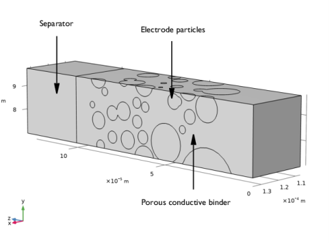
In the Settings window for Complement Selection, type Porous Conductive Binder in the Label text field.
3
Locate the Input Entities section. Click  Add.
4
In the Add dialog box, in the Selections to invert list, choose Particles and Separator.
5
Lithium Foil
1
In the Geometry toolbar, click  Selections and choose Box Selection.
2
In the Settings window for Box Selection, type Lithium Foil in the Label text field.
3
Locate the Geometric Entity Level section. From the Level list, choose Boundary.
4
Locate the Box Limits section. In the z minimum text field, type L_elec+L_sep/2.
5
Locate the Output Entities section. From the Include entity if list, choose Entity inside box.
NMC Current Collector
1
In the Geometry toolbar, click  Selections and choose Box Selection.
2
In the Settings window for Box Selection, type NMC Current Collector in the Label text field.
3
Locate the Geometric Entity Level section. From the Level list, choose Boundary.
4
Locate the Box Limits section. In the z maximum text field, type 0.
5
Locate the Output Entities section. From the Include entity if list, choose Entity inside box.
Particle Boundaries
1
In the Geometry toolbar, click  Selections and choose Adjacent Selection.
2
In the Settings window for Adjacent Selection, type Particle Boundaries in the Label text field.
3
Locate the Input Entities section. Click  Add.
4
In the Add dialog box, select Particles in the Input selections list.
5
6
In the Settings window for Adjacent Selection, locate the Resulting Selection section.
7
From the Show in physics list, choose Off.
Binder Boundaries
1
In the Geometry toolbar, click  Selections and choose Adjacent Selection.
2
In the Settings window for Adjacent Selection, type Binder Boundaries in the Label text field.
3
Locate the Input Entities section. Click  Add.
4
In the Add dialog box, select Porous Conductive Binder in the Input selections list.
5
6
In the Settings window for Adjacent Selection, locate the Resulting Selection section.
7
From the Show in physics list, choose Off.
Particle Surfaces
1
In the Geometry toolbar, click  Selections and choose Intersection Selection.
2
In the Settings window for Intersection Selection, type Particle Surfaces in the Label text field.
3
Locate the Geometric Entity Level section. From the Level list, choose Boundary.
4
Locate the Input Entities section. Click  Add.
5
In the Add dialog box, in the Selections to intersect list, choose Particle Boundaries and Binder Boundaries.
6
Separator + Binder
1
In the Geometry toolbar, click  Selections and choose Union Selection.
2
In the Settings window for Union Selection, type Separator + Binder in the Label text field.
3
Locate the Input Entities section. Click  Add.
4
In the Add dialog box, in the Selections to add list, choose Separator and Porous Conductive Binder.
5
All Domains
1
In the Geometry toolbar, click  Selections and choose Box Selection.
2
In the Settings window for Box Selection, type All Domains in the Label text field.
3
Locate the Box Limits section. In the x minimum text field, type xmin.
4
In the x maximum text field, type xmax.
5
In the y minimum text field, type ymin.
6
In the y maximum text field, type ymax.
7
Locate the Output Entities section. From the Include entity if list, choose All vertices inside box.
8
Locate the Resulting Selection section. From the Show in physics list, choose Off.
All External Boundaries
1
In the Geometry toolbar, click  Selections and choose Adjacent Selection.
2
In the Settings window for Adjacent Selection, type All External Boundaries in the Label text field.
3
Locate the Input Entities section. Click  Add.
4
In the Add dialog box, select All Domains in the Input selections list.
5
Results
Import particle data in the form of a table.
Particle Data Table
1
In the Model Builder window, expand the Results node.
2
Right-click Results>Tables and choose Table.
3
In the Settings window for Table, type Particle Data Table in the Label text field.
Download the data from the entry Particle Statistics (NMC_94wt_0bar) from http://dx.doi.org/10.5905/ethz-iis-1 and import it as a text file to the table.
4
Locate the Data section. Click Import.
For generating the Particles geometry part based on the table data, we will use a model method. Note that the method editor is only available in the Windows® version of the COMSOL Desktop.
Application Builder
In the Home toolbar, click  Application Builder.
New Method
1
In the Application Builder window, right-click Methods and choose New Method.
2
In the New Method dialog box, type GenerateGeometryFromTable in the Name text field.
3
GenerateGeometryFromTable
1
In the Application Builder window, under Methods click GenerateGeometryFromTable.
2
Copy the following code into the GenerateGeometryFromTable window:
// Read data from Results->Table in model builder tree
String tableData[][] = model.result().table().get("tbl1").getTableData(false);

// Read some geometry parameter values from Parameters
Double voxel_size = model.param().evaluate("vox_size");
Double geom_tol = model.param().evaluate("geom_tol");
Double xmin = model.param().evaluate("xmin")+geom_tol;
Double xmax = model.param().evaluate("xmax")+geom_tol;
Double ymin = model.param().evaluate("ymin")+geom_tol;
Double ymax = model.param().evaluate("ymax")+geom_tol;

// Clear geometry part
model.geom("part1").feature().clear();

// Create matrix for added spheres
Double sphereData[][] = new Double[tableData.length][4];
int i = 0; // Row counter for matrix

// Variable for electrode thickness calculation
Double maxz = new Double(0.0);

// Variables for calculating mass-averaged sphere radius
Double Vsum = new Double(0.0);
Double rVsum = new Double(0.0);

// Loop for all rows in the table
for (String[] row : tableData) {
Double xminData = Double.parseDouble(row[2])*voxel_size;
Double yminData = Double.parseDouble(row[3])*voxel_size;
Double xmaxData = Double.parseDouble(row[5])*voxel_size;
Double ymaxData = Double.parseDouble(row[6])*voxel_size;

// Check if within bounding box, and add sphere if radius larger than tolerance
if (((xminData < xmax && xminData > xmin) || (xmaxData < xmax && xmaxData > xmin)) &&
((yminData < ymax && yminData > ymin) || (ymaxData < ymax && ymaxData > ymin))) {
Double volume = Double.parseDouble(row[1])*Math.pow(voxel_size, 3.0);
Double radius = Math.pow(0.75*volume/Math.PI, 0.333333);

if (radius > geom_tol) {
Double xpos = Double.parseDouble(row[8])*voxel_size;
Double ypos = Double.parseDouble(row[9])*voxel_size;
Double zpos = Double.parseDouble(row[10])*voxel_size;

// Add data to sphere data matrix
sphereData[i][0] = xpos;
sphereData[i][1] = ypos;
sphereData[i][2] = zpos;
sphereData[i][3] = radius;
i++;

// Update electrode thickness variable
maxz = maxz < (zpos+radius) ? zpos+radius : maxz;

// Update mass-averaged radius variables if center of sphere inside bounding box
if (((xpos < xmax && xpos > xmin) && (ypos < ymax && ypos > ymin))) {
Vsum = Vsum+volume;
rVsum = rVsum+radius*volume;
}

// Add sphere to part geometry
GeomFeature sph = model.geom("part1").create("sph"+i, "Sphere");
sph.set("pos", new String[]{Double.toString(xpos)+"[m]", Double.toString(ypos)+"[m]", Double.toString(zpos)+"[m]"});
sph.label("Particle "+(int) Math.round(Double.parseDouble(row[0])));
sph.set("r", radius+"[m]");
}
}
}

// Add cylinders to eliminate narrow regions or sharp angles between spheres
double hmin = model.param().evaluate("hmin"); // Minimum mesh element size
int cyl = 1;

// Check distances and gaps between all binary combinations of spheres
for (int j = 0; j < i; j++) {
for (int k = j+1; k < i; k++) {
Double x = sphereData[k][0]-sphereData[j][0];
Double y = sphereData[k][1]-sphereData[j][1];
Double z = sphereData[k][2]-sphereData[j][2];

Double dist = Math.sqrt(x*x+y*y+z*z);

Double gap = dist-(sphereData[k][3]+sphereData[j][3]);
int index1 = sphereData[k][3] < sphereData[j][3] ? k : j;
int index2 = sphereData[k][3] > sphereData[j][3] ? k : j;
Double r_sphere = sphereData[index1][3];

// Add cylinder if spheres are too close or overlapping
if (gap < hmin && gap > -0.667*r_sphere) {

Double x_sphere = sphereData[index1][0];
Double y_sphere = sphereData[index1][1];
Double z_sphere = sphereData[index1][2];

Double direction = sphereData[k][3] < sphereData[j][3] ? -1.0 : 1.0;

Double r_help = r_sphere+gap-hmin;
Double r_cyl = Math.max(Math.sqrt(r_sphere*r_sphere-r_help*r_help), hmin*2);

// Solve root to non-linear equation for cylinder radius (so that sphere-to-sphere distance = hmin along cylinder surface).
Double r1 = r_sphere;
Double r2 = sphereData[index2][3];
double ta = 2*r2;
double tb = 2*r1;
double tc = Math.sqrt(-((gap-hmin+tb+ta)*(gap-hmin+tb)*(gap-hmin+ta)*(gap-hmin)));
r_cyl = ((1/(gap-hmin+r1+r2))*tc)/2;

Double dist_corr = Math.sqrt(r_sphere*r_sphere-r_cyl*r_cyl)-2*hmin;
Double posx = x_sphere+x/dist*dist_corr*direction;
Double posy = y_sphere+y/dist*dist_corr*direction;
Double posz = z_sphere+z/dist*dist_corr*direction;

// Create cylinder
GeomFeature cylinder = model.geom("part1").create("cyl"+cyl++, "Cylinder");
with(cylinder);
set("pos", new String[]{Double.toString(posx)+"[m]", Double.toString(posy)+"[m]", Double.toString(posz)+"[m]"});
set("axistype", "cartesian");
set("ax3", new String[]{Double.toString(x*direction)+"[m]", Double.toString(y*direction)+"[m]", Double.toString(z*direction)+"[m]"});
set("r", r_cyl+"[m]");
set("h", hmin*5+"[m]");
endwith();
}
}
}

// Set electrode length in model
model.param().set("L_elec", maxz+geom_tol+"[m]");

// Build geometry in model
model.geom("part1").run();
model.component("comp1").geom("geom1").run();

// Measure and update volume parameter
model.component("comp1").geom("geom1").measure().selection().init(3);
model.component("comp1").geom("geom1").measure().selection().named("uni1");
model.param().set("Vp", model.geom("geom1").measure().getVolume()+"[m^3]");

// Measure and update area parameter
model.component("comp1").geom("geom1").measure().selection().init(2);
model.component("comp1").geom("geom1").measure().selection().named("intsel1");
model.param().set("Ap", model.geom("geom1").measure().getVolume()+"[m^2]");

// Update mass-averaged radius parameter
model.param().set("rp_avg_spheres", rVsum/Vsum+"[m]");
Methods
In the Home toolbar, click  Model Builder.
Global Definitions
Make the model method available in the model tree, and run it as follows:
Click  Method Call and choose GenerateGeometryFromTable.
Generate Geometry From Particle Data Table
1
In the Model Builder window, under Global Definitions click GenerateGeometryFromTable 1.
2
In the Settings window for Method Call, type Generate Geometry From Particle Data Table in the Label text field.
3
Particles
In the Model Builder window, collapse the Global Definitions>Geometry Parts>Particles node.
Definitions
Finally, update the view so that the y-axis points upwards, and the z-axis to the left, and the x-axis toward you.
1
In the Model Builder window, expand the Component 1 (comp1)>Definitions node.
Camera
1
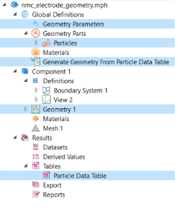
In the Model Builder window, expand the Component 1 (comp1)>Definitions>View 2 node, then click Camera.
2
3
Click the  Zoom Extents button in the Graphics toolbar.
4
In the Settings window for Camera, locate the Position section.
5
In the x text field, type 6.1e-4.
6
In the y text field, type 2.1e-4.
7
In the z text field, type -4.1e-4.
8
Locate the Up Vector section. In the x text field, type 0.
9
In the y text field, type 1.
10
In the z text field, type 0.
11
Click  Update.
12
Click the  Zoom Extents button in the Graphics toolbar.