PDF

Lithium-Ion Battery Seed
Introduction
This is a template model containing the physics, geometry and mesh of a lithium-ion battery. The Lithium-Ion Battery Rate Capability, Lithium-Ion Battery Internal Resistance, 1D Lithium-Ion Battery Drive-Cycle Monitoring, and Diffusion-Induced Stress in a Lithium-Ion Battery applications available in the Applications Library make use of this model setup. Note that the former three applications belong to the category of battery management models.
This model setup is done using the Lithium-Ion Battery interface and incorporates mainly default physical properties. The material properties are taken from the Battery Material Library. As input, you only need to decide upon which initial cell voltage (or initial cell SOC), battery capacity, and thickness of electrodes and separator you want.
Model Definition
The model is set up for a graphite/LMO battery cell. The materials are available from the Battery Material Library and mainly default settings are selected. The model domains consist of:
Negative porous electrode: Graphite (MCMB LixC6) active material and electronic conductor.
Positive porous electrode: LMO (LiMn2O4) active material, electronic conductor, and filler.
Electrolyte: 1.0 M LiPF6 in EC:DEC (1:1 by weight)
This battery cell assembly gives a cell voltage around 4 V, depending on the state-of-charge (SOC) of the cell.
The Lithium-Ion Battery interface accounts for:
An example of parameters that you set on your own for running the model is tabulated in Table 1. The values are selected for a typical 12 Ah graphite/LMO battery cell.
30 μm
55 μm
30 μm
This example utilizes the Initial Cell Charge Distribution global feature. This allows you to set the initial cell voltage (or initial cell state-of-charge (SOC)) as a model input. The feature computes the lithium concentrations (in the case of lithium-ion batteries) in the active electrode materials, cs, and balances the electrodes in the cell to each other. For further reading on this feature, see the Initial Cell Charge Distribution section in the Battery Design Module User’s Guide.
The next section contains a discussion that applies only to the battery management category of models (mentioned above), in which this template model has been used.
Battery Management
This application example is useful for investigation of the following in lithium-ion batteries under isothermal conditions:
Note that one can always make the system nonisothermal with a Heat Transfer interface. In this manner, a sixth property, temperature, may be added to the list above.
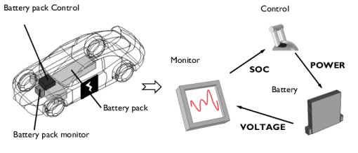
Some of the listed properties play an important part in battery management systems (BMS) in, for instance, electric and hybrid electric vehicles (see Figure 1). The more properties that can be monitored accurately, the easier it is to manage the battery in order to maximize energy output and lifetime, and to guarantee safety.
Figure 1: Electric vehicle with key components within the battery management system visualized. As the flowchart shows to the right, the battery voltage is often monitored and from this the SOC is either computed or determined from empirical data. The information from the monitor determines how the control unit will regulate the battery.
For battery manufacturers, the same properties can be considered when optimizing the design of the battery, for example choice of materials and thickness of electrodes.
Several useful variables are available with the battery management models. For the SOCs of the electrodes, both “coulombic” and “at load” are defined in the Lithium-Ion Battery interface. The “coulombic” in contrast to “at load” omits the impact of any polarization in the battery. This means that the “coulombic” type is based on the average concentration in the particle and the “load” on the particle surface concentration.
SOC, coulombic, in each electrode:
(1)
SOC, at load, in each electrode:
(2)
The cell SOC can likewise by either “coulombic” or “at load”. The cell SOC, coulombic, is computed in the model as:
(3)
where the average cyclable lithium concentration in the electrode particles is inserted which is defined as:
(4)
Cell SOC, at load, is computed as:
(5)
where the cyclable lithium concentration at the surface of the electrode particles is inserted which is defined as:
(6)
The SOC definitions are furthermore used to compute the coulombic or at load open-circuit potential of each electrode and the corresponding open-circuit cell voltages.
Additionally, the model also sets up the local potential in the solid and electrolyte phases to calculate the cell voltage, Ecell, and the potential of each electrode, E, during load, as shown in Equation 7 and Equation 8.
(7)
(8)
Here, “cc” denotes the current collector boundary and “sep” the separator boundary.
The total polarization is determined in the model as well. It is calculated as the difference between the cell voltage and open-circuit cell voltage (coulombic).
(9)
In the same way, the electrodes’ polarization can be obtained as the difference between the electrode potential and open-circuit potential (coulombic).
Study Settings
In order for the Initial Cell Charge Distribution feature to function a Current Distribution Initialization study step is required.
Reference
1. M. Doyle, and Y. Fuentes, “Computer Simulations of a Lithium-Ion Polymer Battery and Implications for Higher Capacity Next-Generation Battery Designs,” J. Electrochem. Soc., vol. 150, no. 6, pp. A706–A713, 2003.
Application Library path: Battery_Design_Module/Batteries,_Lithium-Ion/li_battery_seed
Modeling Instructions
From the File menu, choose New.
New
In the New window, click  Model Wizard.
Model Wizard
1
In the Model Wizard window, click  1D.
2
In the Select Physics tree, select Electrochemistry>Batteries>Lithium-Ion Battery (liion).
3
Click Add.
4
Click  Study.
5
In the Select Study tree, select Preset Studies for Selected Physics Interfaces>Time Dependent with Initialization. This study step automatically computes the initial potentials in the cell.
6
Global Definitions
This model mainly uses the input of default parameters. However, the battery capacity and its initial voltage, together with the thicknesses of the electrodes and the separator are required to be set.
Parameters 1
1
In the Model Builder window, under Global Definitions click Parameters 1.
2
In the Settings window for Parameters, locate the Parameters section.
3
Add Material
The model has a graphite negative electrode, a LMO positive electrode, and a LiPF6 1:1 EC:DEC electrolyte. Import the materials from the Battery Material Library.
1
In the Home toolbar, click  Add Material to open the Add Material window.
2
Go to the Add Material window.
3
In the tree, select Battery>Electrolytes>LiPF6 in 1:1 EC:DEC (Liquid, Li-ion Battery).
4
Click the right end of the Add to Component split button in the window toolbar.
5
From the menu, choose Add to Global Materials.
6
In the tree, select Battery>Electrodes>Graphite, LixC6 MCMB (Negative, Li-ion Battery).
7
Click the right end of the Add to Component split button in the window toolbar.
8
From the menu, choose Add to Global Materials.
9
In the tree, select Battery>Electrodes>LMO, LiMn2O4 Spinel (Positive, Li-ion Battery).
10
Click the right end of the Add to Component split button in the window toolbar.
11
From the menu, choose Add to Global Materials.
12
In the Home toolbar, click  Add Material to close the Add Material window.
Definitions
Cell voltage probe
1
In the Definitions toolbar, click  Probes and choose Global Variable Probe.
2
In the Settings window for Global Variable Probe, type Cell voltage probe in the Label text field.
3
Locate the Expression section. In the Expression text field, type Ecell.
Geometry 1
Interval 1 (i1)
1
In the Model Builder window, under Component 1 (comp1) right-click Geometry 1 and choose Interval.
2
In the Settings window for Interval, locate the Interval section.
3
From the Specify list, choose Interval lengths.
4
5
Click  Build Selected.
Definitions
Explicit selections are made in the model geometry.
Negative electrode
1
In the Definitions toolbar, click  Explicit.
2
In the Settings window for Explicit, type Negative electrode in the Label text field.
3
Separator
1
In the Definitions toolbar, click  Explicit.
2
3
In the Settings window for Explicit, type Separator in the Label text field.
Positive electrode
1
In the Definitions toolbar, click  Explicit.
2
3
In the Settings window for Explicit, type Positive electrode in the Label text field.
Integration 1 (intop1)
1
In the Definitions toolbar, click  Nonlocal Couplings and choose Integration.
2
In the Settings window for Integration, type negative in the Operator name text field.
3
Locate the Source Selection section. From the Selection list, choose Negative electrode.
Integration 2 (intop2)
1
In the Definitions toolbar, click  Nonlocal Couplings and choose Integration.
2
In the Settings window for Integration, type positive in the Operator name text field.
3
Locate the Source Selection section. From the Selection list, choose Positive electrode.
Integration 3 (intop3)
Select the end-terminal boundary, that is, the positive electrode current collector, along with the rest of the electrode boundaries.
1
In the Definitions toolbar, click  Nonlocal Couplings and choose Integration.
2
In the Settings window for Integration, type pos_cc in the Operator name text field.
3
Locate the Source Selection section. From the Geometric entity level list, choose Boundary.
4
Integration 4 (pos_cc2)
1
Right-click Integration 3 (intop3) and choose Duplicate.
2
In the Settings window for Integration, type neg_cc in the Operator name text field.
3
Integration 5 (neg_cc2)
1
Right-click Integration 4 (pos_cc2) and choose Duplicate.
2
In the Settings window for Integration, type neg_sep in the Operator name text field.
3
Integration 6 (neg_sep2)
1
Right-click Integration 5 (neg_cc2) and choose Duplicate.
2
In the Settings window for Integration, type pos_sep in the Operator name text field.
3
Materials
Material Link 1 (matlnk1)
In the Model Builder window, under Component 1 (comp1) right-click Materials and choose More Materials>Material Link.
Material Link 2 (matlnk2)
1
Right-click Materials and choose More Materials>Material Link.
2
In the Settings window for Material Link, locate the Link Settings section.
3
From the Material list, choose Graphite, LixC6 MCMB (Negative, Li-ion Battery) (mat2).
Material Link 3 (matlnk3)
1
Right-click Materials and choose More Materials>Material Link.
2
In the Settings window for Material Link, locate the Link Settings section.
3
From the Material list, choose LMO, LiMn2O4 Spinel (Positive, Li-ion Battery) (mat3).
Lithium-Ion Battery (liion)
Add the three typical battery domains in the Lithium-Ion Battery interface: a negative porous electrode, a positive porous electrode, and a separator.
Porous Electrode 1
For the negative electrode, select material properties where possible. Change the negative electrode particle radius. The initial concentration of lithium in graphite is calculated further on.
1
In the Model Builder window, under Component 1 (comp1) right-click Lithium-Ion Battery (liion) and choose Porous Electrode.
2
In the Settings window for Porous Electrode, locate the Domain Selection section.
3
From the Selection list, choose Negative electrode.
4
Locate the Electrolyte Properties section. From the Electrolyte material list, choose Material Link 1 (matlnk1).
5
Locate the Electrode Properties section. From the Electrode material list, choose Material Link 2 (matlnk2).
Particle Intercalation 1
1
In the Model Builder window, click Particle Intercalation 1.
2
In the Settings window for Particle Intercalation, locate the Material section.
3
From the Particle material list, choose Material Link 2 (matlnk2).
4
Locate the Particle Transport Properties section. In the rp text field, type 2e-6[m].
Porous Electrode Reaction 1
1
In the Model Builder window, click Porous Electrode Reaction 1.
2
In the Settings window for Porous Electrode Reaction, locate the Material section.
3
From the Material list, choose Material Link 2 (matlnk2).
Porous Electrode 2
Select material properties for the positive electrode as well. Change the positive electrode particle radius. The initial concentration of lithium in LMO is calculated further on.
1
In the Physics toolbar, click  Domains and choose Porous Electrode.
2
In the Settings window for Porous Electrode, locate the Domain Selection section.
3
From the Selection list, choose Positive electrode.
4
Locate the Electrolyte Properties section. From the Electrolyte material list, choose Material Link 1 (matlnk1).
5
Locate the Electrode Properties section. From the Electrode material list, choose Material Link 3 (matlnk3).
Particle Intercalation 1
1
In the Model Builder window, click Particle Intercalation 1.
2
In the Settings window for Particle Intercalation, locate the Material section.
3
From the Particle material list, choose Material Link 3 (matlnk3).
4
Locate the Particle Transport Properties section. In the rp text field, type 2e-6[m].
Porous Electrode Reaction 1
1
In the Model Builder window, click Porous Electrode Reaction 1.
2
In the Settings window for Porous Electrode Reaction, locate the Material section.
3
From the Material list, choose Material Link 3 (matlnk3).
Separator 1
Since a liquid electrolyte is chosen, the battery model requires a separator.
1
In the Physics toolbar, click  Domains and choose Separator.
2
In the Settings window for Separator, locate the Domain Selection section.
3
From the Selection list, choose Separator.
4
Locate the Electrolyte Properties section. From the Electrolyte material list, choose Material Link 1 (matlnk1).
Select the global feature Initial Cell Charge Distribution to allow either cell voltage or cell state-of-charge initially as input. The feature computes the initial lithium concentration in the electrode materials and balances the electrodes by computing the electrode material volume fraction in each electrode.
Initial Cell Charge Distribution 1
1
In the Physics toolbar, click  Global and choose Initial Cell Charge Distribution.
Since it is a lithium-ion battery chemistry with a negative carbon electrode, the default fractions in the Battery Cell Electrode Balancing section can be kept.
2
In the Settings window for Initial Cell Charge Distribution, locate the Battery Cell Parameters section.
3
In the Ecell,0 text field, type Ecell_init.
4
In the Qcell,0 text field, type Q_B.
Negative Electrode Selection 1
Select which model domains that represent the negative and positive electrode, respectively.
1
In the Model Builder window, expand the Initial Cell Charge Distribution 1 node, then click Negative Electrode Selection 1.
2
Positive Electrode Selection 1
1
In the Model Builder window, click Positive Electrode Selection 1.
2
Porous Electrode 1
To balance the electrodes in the cell and optimize the electrode material usage for the electrodes, revisit the Porous Electrode nodes and enter the electrode material volume fractions computed by the Initial Cell Charge Distribution feature.
1
In the Model Builder window, under Component 1 (comp1)>Lithium-Ion Battery (liion) click Porous Electrode 1.
2
In the Settings window for Porous Electrode, locate the Porous Matrix Properties section.
3
In the εs text field, type liion.epss_neg.
4
In the εl text field, type 1-liion.epss_neg.
Porous Electrode 2
1
In the Model Builder window, click Porous Electrode 2.
2
In the Settings window for Porous Electrode, locate the Porous Matrix Properties section.
3
In the εs text field, type liion.epss_pos.
4
In the εl text field, type 1-liion.epss_pos.
Electric Ground 1
Finish by setting the boundary conditions. Ground is set as reference at the leftmost boundary, the negative electrode current collector. A current is applied at the rightmost boundary, the positive electrode current collector. Set for instance the 1C discharge rate with the 1C current available with the Initial Cell Charge Distribution feature.
1
In the Physics toolbar, click  Boundaries and choose Electric Ground.
2
Electrode Current 1
1
In the Physics toolbar, click  Boundaries and choose Electrode Current.
2
3
In the Settings window for Electrode Current, locate the Electrode Current section.
4
In the Is,total text field, type -liion.I_1C.