Diffuse Surface (Surface-to-Surface Radiation Interface)
Diffuse surfaces reflect radiative intensity uniformly in all directions. This node handles radiation with a view factor calculation. It is assumed that no radiation is transmitted through the surface. The feature adds one radiosity shape function per spectral interval to its selection and uses it as surface radiosity.
It adds a radiative heat source contribution
on the side of the boundary where the radiation is defined, where ε is the surface emissivity, G is the irradiation, and eb(T) is the blackbody hemispherical total emissive power. Where the radiation is defined on both sides, the radiative heat source is defined on both sides too.
If specular reflection should be considered, use the Opaque Surface (Surface-to-Surface Radiation Interface) node instead.
If specular reflection and transmission should be considered, use the Semitransparent Surface (Surface-to-Surface Radiation Interface) node instead.
If no emission should be considered, use the Diffuse Mirror (Surface-to-Surface Radiation Interface) node instead.
Model Input
This section has fields and values that are inputs to expressions that define material properties. If such user-defined property groups have been added, the model inputs are included here.
There is one standard model input: the Temperature T is used in the expression of the blackbody radiation intensity and when multiple wavelength intervals are used, for the fractional emissive power. The temperature model input is also used to determine the variable that receives the radiative heat source. When the model input does not contain a dependent variable, the radiative heat source is ignored.
The default Temperature is User defined. When additional physics interfaces are added to the model, the temperature variables defined by these physics interfaces can also be selected from the list. The Common model input option corresponds to the minput.T variable, set to 293.15 K by default) and all temperature variables from the physics interfaces included in the model. To edit the minput.T variable, click the Go to Source button (), and in the Default Model Inputs node under Global Definitions, set a value for the Temperature in the Expression for remaining selection section.
Radiation Direction
When Wavelength dependence of radiative properties is set to Constant in the Radiation Settings section of the physics interface, select an Emitted radiation direction based on the geometric normal (nxnynz): Opacity controlled (default), Negative normal direction, Positive normal direction, Both sides, or None.
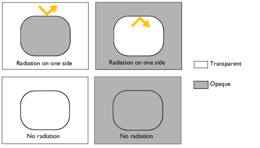
Opacity controlled requires that each boundary is adjacent to exactly one opaque domain. Opacity is controlled by the Opacity (Surface-to-Surface Radiation Interface) domain feature. For external boundaries, the exterior side opacity is transparent by default but may be edited by setting the Selection of the Opacity feature on All voids in the Opacity feature. Figure 6-1 illustrates the emitted radiation direction depending on the opacity of the adjacent domain.
Figure 6-1: Emitted radiation direction with the option Opacity controlled.
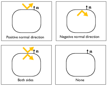
Select Negative normal direction to specify that the surface radiates in the negative normal direction (un vector direction). An arrow indicates the negative normal direction that corresponds to the direction of the radiation emitted by the surface. Figure 6-2 illustrates the emitted radiation direction depending on the chosen option.
Select Positive normal direction if the surface radiates in the positive normal direction (dn vector direction). An arrow indicates the positive normal direction that corresponds to the direction of the radiation emitted by the surface. Figure 6-2 illustrates the emitted radiation direction depending on the chosen option.
Select Both sides if the surface radiates on both sides. Figure 6-2 illustrates the emitted radiation direction depending on the chosen option.
Select None when adjacent domains are either both transparent or both opaque for a given spectral band. When the Emitted radiation direction is set to None for a spectral band, the radiative properties set for this spectral band are not used
Figure 6-2: Emitted radiation direction with Positive normal direction, Negative normal direction and Both sides options.
When Wavelength dependence of radiative properties is set to Solar and ambient or Multiple spectral bands in the Radiation Settings section of the physics interface, select an Emitted radiation direction for each spectral band: Opacity controlled (default), Negative normal direction, Positive normal direction, Both sides, or None. The Emitted radiation direction defines the radiation direction for each spectral band similarly as when Wavelength dependence of radiative properties is Constant. Defining a radiation direction for each spectral band makes it possible to build models where the transparency or opacity properties defers between spectral bands.
Note that when Wavelength dependence of radiative properties is set to Solar and ambient or Multiple spectral bands, the upper bound of the last spectral band, meant to represent the infinite, is set to 1[mm], for the computation of the surface material properties.
Ambient
Select the Define ambient properties on each side check box when the ambient properties differs between the sides of a boundary. This is needed to define ambient temperature for a surface that radiates on both sides and that is exposed to a hot temperature on one side (for example, fire) and to a cold temperature on the other side (for example, external temperature). By default, Define ambient properties on each side is not selected.
Ambient Temperature
The ambient temperature Tamb should be set for the computation of eb(Tamb), the ambient blackbody hemispherical total emissive power, used for the evaluation of the ambient irradiation Gamb=Fambεambeb(Tamb).
Set the Ambient temperature Tamb. For User defined, enter a value or expression. Else, select an Ambient temperature defined in an Ambient Properties node under Definitions. When Define ambient properties on each side is selected, define the Ambient temperature, upside Tambu and Ambient temperature, downside Tambd, respectively. The geometric normal points from the downside to the upside.
Set Tamb to the far-away temperature in directions where no other boundaries obstruct the view. Inside a closed cavity, the ambient view factor, Famb, is theoretically zero and the value of Tamb therefore should not matter. It is, however, good practice to set Tamb to T or to a typical temperature value for the cavity surfaces in such cases because that minimizes errors introduced by the finite resolution of the view factor evaluation.
Ambient Emissivity
The ambient emissivity εamb should be set for the computation of the ambient irradiation Gamb=Fambεambeb(Tamb).
The Ambient emissivity εamb should be specified. When Blackbody is selected, the ambient emissivity is set to 1 for the computation of the ambient irradiation Gamb.
If Wavelength dependence of radiative properties is Constant, choose alternatively the User defined option, and set a value or expression. You can define a temperature-dependent emissivity using the variable rad.T.
If Wavelength dependence of radiative properties is Solar and ambient or Multiple spectral bands, the ambient irradiation Gamb,i of each spectral band i is calculated:
When Ambient emissivity is set to User defined, enter a value or expression for the Ambient emissivity εamb. The wavelength may be accessed through the rad.lambda variable. Any expression set for the emissivity is then averaged on each spectral band to obtain a piecewise constant emissivity, with values εamb,i. If the average value of the emissivity on each band εamb,i is known, you may use instead the User defined for each band option to avoid the evaluation of the average.
When Ambient emissivity is set to User defined for each band, enter a value for the Ambient emissivity εamb,i for each spectral band. Within a spectral band, each value is assumed to be independent of wavelength.
When Define ambient properties on each side is selected, define the Ambient emissivity, upside εambu and Ambient emissivity, downside εambd, respectively. The geometric normal points from the downside to the upside.
Diffuse Irradiance
When the Include diffuse irradiance check box is selected, a diffuse irradiation contribution Idiff is included into the external irradiation. When considering solar irradiation, it takes into account the irradiation from the sun, scattered by the atmosphere, and assumed to be isotropic.
When Diffuse irradiance is set to User defined, enter a value or expression for the diffuse irradiance.
When Diffuse irradiance is set to User defined for each band, enter a value or expression for the diffuse irradiance for each spectral band.
Select a Clear sky noon diffuse horizontal irradiance defined in an Ambient Properties node under Definitions to define the diffuse irradiance from ambient properties.
To consider only the direct irradiation defined in the External Radiation Source feature, clear the Include diffuse irradiance check box.
Fractional Emissive Power
This section is available when the Wavelength dependence of radiative properties is defined as Solar and ambient or Multiple spectral bands for the physics interface (see Radiation Settings).
When the Fractional emissive power is Blackbody/Graybody, the fractional emissive power is automatically calculated for each spectral band as a function of the band endpoints and surface temperature.
When the Fractional emissive power is User defined for each band, define the Fractional emissive power, FEPi for each spectral band. All fractional emissive powers are expected to be in [0,1] and their sum is expected to be equal to 1. Select the Define fractional emissive power on each side check box to set specific Upside and Downwside values in the table.
Surface Emissivity
If Wavelength dependence of radiative properties is Constant:
By default, the Emissivity ε (dimensionless) uses values From material. This is a property of the material surface that depends both on the material itself and the structure of the surface. Make sure that a material is defined at the boundary level (by default materials are defined at the domain level).
For User defined, set a value or expression. You can define a temperature-dependent emissivity using the variable rad.T.
Select the Define properties on each side check box to set specific values for the radiative properties on each side. Select the Boundary material, upside and Boundary material, downside to have different material properties on each side. The boundary material specified is used only when Emissivity, upside or Emissivity, downside are From material.
If Wavelength dependence of radiative properties is Solar and ambient or Multiple spectral bands:
By default, the Emissivity ε (dimensionless) uses values From material.
When Emissivity is set to User defined, enter a value or expression for the Emissivity ε. The wavelength may be accessed through the rad.lambda variable. Any expression set for the emissivity is then averaged on each spectral band to obtain a piecewise constant emissivity. If the average value of the emissivity on each band is known, you may use instead the User defined for each band option to avoid the evaluation of the average.
When Emissivity is set to User defined for each band, enter a value for the Emissivity for each spectral band. Within a spectral band, each value is assumed to be independent of wavelength. By default, the same emissivity is defined on both sides. Select the Define properties on each side check box and fill the Upside and Downside columns of the table for a specific definition on each side.
Set the surface emissivity to a number between 0 and 1, where 0 represents diffuse mirror and 1 is appropriate for a perfect blackbody. The proper value for a physical material lies somewhere in between and can be found from tables or measurements.
In the notation used here, Bi stands for B1, B2,... up to the maximum number of spectral intervals.
To define temperature dependencies for the user inputs (surface emissivity for example), use the temperature variable ht.T, that corresponds to the appropriate variable (upside, downside, or average temperature of a layer, wall temperature with turbulence modeling), depending on the model configurations. See Boundary Wall Temperature for a thorough description of the boundary temperature variables.
Several settings for this node depend on the Wavelength dependence of radiative properties setting, which is defined for the physics interface.
In addition, the Transparent media refractive index is equal to 1 by default.
Upside and downside settings can be visualized by plotting the global normal vector (nx, ny, nz), that always points from downside to upside. Note that the normal vector (ht.nx, ht.ny, ht.nz) may be oriented differently.
See Tangent and Normal Variables in the COMSOL Multiphysics Reference Manual.
Heat Generation in a Disc Brake: Application Library path Heat_Transfer_Module/Thermal_Contact_and_Friction/brake_disc
Location in User Interface
Context Menus
Ribbon
Physics tab with Surface-to-Surface Radiation selected: