Boundary Wall Temperature
Depending on the model configuration, a single temperature field per boundary may not be sufficient to model accurately the temperature. In some cases, different dependent variables are used to compute the temperature in the wall, at the wall sides, or in the turbulent boundary layer. This section describes when additional degrees of freedom are needed and how they are handled.
The boundary temperature variable called ht.Tvar describes the wall temperature. When the wall has a nonconstant temperature across its thickness, this variable contains the average value between the temperatures of the two sides of the wall. The actual definition of ht.Tvar depends on the model configuration.
Some features define a local temperature: ht.feat1.Tvar. For example, when a boundary heat source is applied on a particular side of the layer, this local variable ht.bhs1.Tvar contains either the temperature upside or downside the boundary.
The following list includes existing boundary temperature variables that are available depending on the model configuration:
T: general temperature variable that coincides with the wall temperature in most cases
TWall_u: upside wall temperature defined by a Wall or an Interior Wall feature with turbulence only if a Fluid feature is defined on the upside of the wall.
TWall_d: downside wall temperature defined by a Wall or an Interior Wall feature with turbulence only if a Fluid feature is defined on the downside of the wall.
Tu: temperature on the upside of the boundary.
Td: temperature on the downside of the boundary.
TExtFace: external temperature of an external boundary defined by a thermally thick boundary condition.
TuWF: temperature of the fluid in the turbulent boundary layer near the wall only if the Fluid feature is defined on the upside of the Wall feature.
TdWF: temperature of the fluid in the turbulent boundary layer near the wall only if the Fluid feature is defined on the downside of the Wall feature.
The values of these variables depend on the selections where they are defined. Here are some illustrated cases:
Depending on the turbulence model selected for the flow, wall functions are used or not:
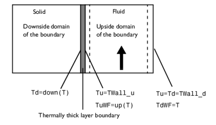
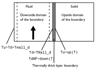
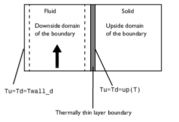
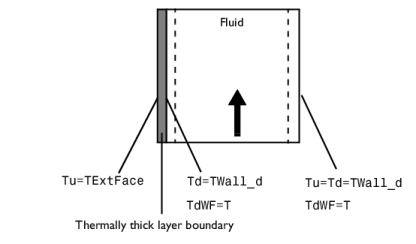
Turbulence models: wall functions detected by the Single Phase Flow physics interface. TuWF and TdWF have different definitions and a flux qwf is applied on the wall boundaries. See Temperature Condition for Automatic Wall Treatment and Wall functions in the CFD Module User’s Manual for details.
The following sections summarize the definitions of the temperature variables for the abovementioned configurations.
Intersection Between a Wall Boundary Feature Selection and Interface Exterior Boundaries
The following figure shows a configuration with a fluid domain, a thermally thick boundary condition on the left boundary, and a Wall feature on the right boundary. This example uses wall functions.
Interface Between a Fluid Domain Feature and a Solid Domain Feature Where a Wall Boundary Feature Is Active
Solid in the Domain Downside the Wall
The following figures show configurations with a solid as downside domain and a fluid as upside domain with either a thermally thick or thermally thin boundary condition in between. This example uses wall functions.
Solid in the Domain Upside the Wall
The following figures show configurations with a fluid as downside domain and a solid as upside domain with either a thermally thick or thermally thin boundary condition in between. This example uses wall functions.
Interface Between two Fluid Domain Features Where an Interior Wall Boundary Feature Is Active
The following figure shows a configuration with two fluid domains with a thermally thick boundary condition and an Interior Wall feature in between. This example uses wall functions.