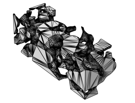
Use an Import node (

) to import a mesh from a
3MF,
PLY,
STL, or
VRML file. When you import a mesh, you can position, rotate, and scale the mesh by using one or several
Transform attributes.

To import additional meshes, add another Import node. Then COMSOL Multiphysics adds the elements of the newly imported mesh to the existing mesh.
The Import operation will change the number of entities in the mesh, so unless the meshing sequence is defining its own geometric model, a new meshing sequence of this type will be set up automatically. Then, the
Import node will be added in the new sequence.
Specify the filename in the Filename field or click the
Browse button. You can also click the downward arrow beside the
Browse button and choose
Browse From (

) to open the fullscreen
Select File window. Click the downward arrow for the
File Location Actions menu (

) to choose
Show in Auxiliary Data (

) to move to the row for this file in the
Auxiliary Data window,
Copy File Location (

), and (if you have copied a file location)
Paste File Location (

).
If you have changed some property, the software automatically reimports the mesh when you click a build button. For import of a meshing sequence, select Build source mesh automatically (selected by default) to automatically build the source sequence and reimport the current version of the mesh. This is required when running a parametric sweep over some parameter that affects the source mesh.
These settings are available when the Source list is set to
STL file for import of stereolithography files in 3D. Such files contain data for an unstructured triangulated surface.
The Create selections check box is selected by default to create a boundary selection of every
solid section in the file during import. Typically, there is only one such section. In that case, a selection of the entire boundary is created. This happens also when the STL file is binary and can by definition have no
solid sections. The created selections appear in a table in the
Boundary Selections section that appears below the
Import section. The table has two columns. In the right column, the name of the
solid section that the selection has been created from appears. If the section is unnamed or if the file is binary, the name is empty. The selections appear in the same order as the corresponding sections in the file. In the left column, the name of the selection appears. By this name, which can be changed, as well as dimension of the selection, you can find the selection in the model.

