Cross Grating
Use the Cross Grating node to treat a boundary as a diffraction grating that can release reflected and transmitted rays into multiple diffraction orders. Unlike a standard Grating, a Cross Grating can have two directions of periodicity; the boundary is treated as a general two-dimensional periodic substructure. A Diffraction Order (Cross Grating) subnode for reflected and transmitted rays in order m = n = 0 is added by default. Change the settings for this default subnode to release rays into different diffraction orders. You can also release rays of multiple diffraction order pairs from the same boundary by adding more Diffraction Order subnodes from the from the context menu (right-click the parent node) or from the Physics toolbar, Attributes menu.
The Accumulator (Boundary) subnode is also available from the context menu (right-click the parent node) or from the Physics toolbar, Attributes menu.
Releasing Secondary Rays
When two or more rays are released from a Cross Grating boundary, one of the released rays uses the same degrees of freedom as the incident ray. The remaining degrees of freedom must be preallocated in memory as secondary rays. The total number of secondary rays that can be released in the model is controlled by the Maximum number of secondary rays field in the physics interface Ray Release and Propagation section. See the Grating feature for further details.
Device Properties
Select an option from the Rays to release list: Reflected and transmitted (the default), Reflected, or Transmitted. Then enter the Grating constant, direction 1 d1 (SI unit: m) and the Grating constant, direction 2 d2 (SI unit: m). The defaults are d1 = 1 μm and d2 = 2 μm.
If the ray power is solved for, the Store total transmitted power and Store total reflected power check boxes are shown. Select them to declare auxiliary dependent variables for the total power of all transmitted and reflected diffraction orders, respectively.
Grating Orientation
The Cross Grating requires two grating orientations to be specified. For each of Grating orientation 1 and Grating orientation 2 select either Specify direction of periodicity (the default) or Specify direction of grating lines. The Grating orientation 2 may also be Orthogonal to grating orientation 1.
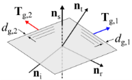
If Specify direction of periodicity is selected, select an option from the Direction of periodicity 1 (or 2) list: User defined (the default) or Parallel to reference edge. For User defined enter the components of the direction of periodicity Tp,1 or Tp,2 (dimensionless) directly. The defaults for Tp,1 and Tp,2 are the positive x-axis and positive y-axis respectively. For Parallel to reference edge, the Reference Edge Selection, Direction 1 and/or Reference Edge Selection, Direction 2 sections are shown. Select a single edge (for each direction), which must be adjacent to at least one boundary in the selection for the Cross Grating feature and not parallel to each other.
If Specify direction of grating lines is selected, select an option from the Direction of grating lines 1 (or 2) list: User defined (the default) or Parallel to reference edge. For User defined enter the components of the direction of grating lines Tl,1 or Tl,2 (dimensionless) directly. The defaults for Tl,1 and Tl,2 are the positive y-axis and positive x-axis respectively. For Parallel to reference edge, the Reference Edge Selection, Direction 1 and/or Reference Edge Selection, Direction 2 sections are shown. Select a single edge (for each direction), which must be adjacent to at least one boundary in the selection for the Cross Grating feature and not parallel to each other.
Similar to the Grating, regardless of the grating orientations are specified, the directions of periodicity projected onto the grating surface Tg,1 and Tg,2 will be computed. This is shown in Figure 3-12, along with typical paths for incident reflected, and transmitted rays.
Figure 3-12: Diagram illustrating the cross grating orientation. The directions of periodicity and/or lines (which need not be orthogonal) are projected onto the cross grating surface.