You are viewing the documentation for an older COMSOL version. The latest version is
available here.
Use the Grating node to treat a boundary as a diffraction grating that can release reflected and transmitted rays into multiple diffraction orders. A
Diffraction Order (Grating) subnode for reflected and transmitted rays of order
m = 0 is added by default. Change the settings for this default subnode to release rays of a different diffraction order. You can also release rays of multiple diffraction orders from the same boundary by adding more
Diffraction Order subnodes from the from the context menu (right-click the parent node) or from the
Physics toolbar,
Attributes menu.
The Accumulator (Boundary) subnode is also available from the context menu (right-click the parent node) or from the
Physics toolbar,
Attributes menu.
When two or more rays are released from a Grating boundary, one of the released rays uses the same degrees of freedom as the incident ray. The remaining degrees of freedom must be preallocated in memory as secondary rays. The total number of secondary rays that can be released in the model is controlled by the
Maximum number of secondary rays field in the physics interface
Ray Release and Propagation section.
For example, if both reflected and transmitted rays of diffraction orders m = −1,
m = 0, and
m = 1 are released from a boundary, then for every incident ray, a total of five secondary rays are released. If the diffraction order
m = −1 is the first subnode to appear in the Model Builder, then the transmitted ray of order
m = −1 uses the same degree of freedom as the incident ray, and the other rays are secondary rays. If the
Maximum number of secondary rays is
500 and more than
100 rays interact with the grating, then no more secondary rays are emitted and a warning is generated by the solver, indicating that the
Maximum number of secondary rays should be increased.
Select an option from the Rays to release list:
Reflected and transmitted (the default),
Reflected, or
Transmitted. Then enter the a
Grating constant d (SI unit: m), which is the distance between consecutive lines in the grating, i.e. the length of one unit cell. The default is
5 µm.
Select Use relative order numbers if the grating blaze angle is known, and diffraction into the highest-efficiency orders is desired. Then enter the
Grating blaze angle θB (SI unit: rad). The default is 0. The absolute order number will be computed based on the blaze angle and the refractive indices of the adjacent domains.
If Use relative order numbers is not selected, then the
Automatic Diffraction Order Calculation section will be present. This will be discussed below.
If the ray power is solved for, the Store total transmitted power and
Store total reflected power check boxes are shown. Select them to declare auxiliary dependent variables for the total power of all transmitted and reflected diffraction orders, respectively.
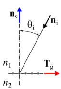
In 2D, select an option from the Direction of periodicity list:
Forward (the default) or
Reverse. For either setting, an arrow appears in the Graphics window, lying tangent to the selected edges. Reflected and refracted rays from positive diffraction orders have a larger ray direction component in the direction of this arrow, compared to rays from negative diffraction orders.
In 3D, select an option from the Grating orientation list:
Specify direction of periodicity (the default) or
Specify direction of grating lines.
|
•
|
If Specify direction of periodicity is selected, select an option from the Direction of periodicity list: User defined (the default) or Parallel to reference edge. For User defined enter the components of the direction of periodicity Tp (dimensionless) directly. The default is the positive x-axis. For Parallel to reference edge, the Reference Edge Selection section is shown in the Settings window. Select a single edge, which must be adjacent to at least one boundary in the selection for the Grating feature.
|
|
•
|
If Specify direction of grating lines is selected, select an option from the Direction of grating lines list: User defined (the default) or Parallel to reference edge. For User defined enter the components of the direction of grating lines Tl (dimensionless) directly. The default is the positive y-axis. For Parallel to reference edge, the Reference Edge Selection section is shown in the Settings window. Select a single edge, which must be adjacent to at least one boundary in the selection for the Grating feature.
|
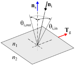
Regardless of how Tp or
Tl has been specified, the direction of periodicity projected onto the grating surface
Tg will be computed. This is shown in
Figure 3-8 for 2D and
Figure 3-9 for 3D.
|
|
The Automatic Diffraction Order Calculation section is not shown if the Use relative order numbers check box is selected; see the Device Properties section.
|
Use the Add Diffraction Orders button to automatically add diffraction orders to the
Grating feature. The other settings in this section allow you to automatically generate the diffraction orders that would be produced by a ray of specified wavelength at a specified angle of incidence. The recommended workflow is to first configure all of the inputs in this section, and then click
Add Diffraction Orders.
For each diffraction order a corresponding Diffraction Order (Grating) subnode will be added to this node. If some
Diffraction Order subnodes are already present, then clicking
Add Diffraction Orders will delete them and replace them with the automatically generated nodes. A warning will be issued if this operation might result in the creation of a very large number of subnodes.
From the Automatic diffraction order type list select either
Specify minimum wavelength (the default) or
Specify maximum frequency. The
Minimum wavelength or
Maximum frequency can be either taken
From Physics (the default) or
User defined. If
From Physics is selected, then the algorithm that generates the diffraction orders will first search through all ray release features to determine the minimum wavelength.
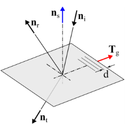
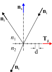
In addition, specify the Angle of incidence θi (SI unit: rad). In 3D, instead enter both the
Angle of incidence, in plane θi,in (SI unit: rad) and the
Angle of incidence, out of plane θi,out (SI unit: rad). Also enter the
Refractive index, incoming n1 and
Refractive index, outgoing n2. The defaults are 0. If the
Rays to release are
Reflected then
n2 = n1. See
Figure 3-10 and
Figure 3-11 for details.