PDF

Glazing Influence on Thermal Performances of a Window
Introduction
During the design of a building, environmental issues have gained considerable influence in the entire project. One of the first concerns is to improve thermal performances. In this process, simulation software provide key tools for modeling thermal losses and performances in the building
The international standard ISO 10077-2:2012 (Ref. 1) deals with thermal performances of windows, doors, and shutters. It provides computed values of the thermal characteristics of frame profiles in order to validate a simulation software.
COMSOL Multiphysics successfully passes the entire benchmark. This document describes two test cases of ISO 10077-2:2012 related to the glazing influence on thermal performances of a window. Other test cases from this standard are available in the following applications:
Figure 1: Geometry of the window and cross-section view.
Model Definition
On each test case, a window section separates a hot internal side from a cold external side. The window frame is the same but in the first application, an insulation panel replaces the traditional glazing. This traditional glazing is tackled in the second application. After solving a model, two quantities are calculated and compared to the normative values:
air cavities
A window frame contains many cavities. The purpose is to ensure thermal insulation. According to the standard, cavities are modeled in different ways depending on their shapes.
The heat flow rate in cavities is represented by an equivalent thermal conductivity keq, which includes the heat flow by conduction, convection, and radiation. It also depends on the geometry of the cavity and on the adjacent materials. The definition of keq is detailed in the next paragraphs.
Cavities are divided into three types:
unventilated cavities, completely closed or connected either to the exterior or to the interior by a slit with a width not exceeding 2 mm;
slightly ventilated cavities, connected either to the exterior or to the interior by a slit greater than 2 mm but not exceeding 10 mm;
well-ventilated cavities, corresponding to a configuration not covered by one of the two preceding types, it is assumed that the whole surface is exposed to the environment so that boundary conditions are applied to (see the Boundary conditions section below for more information).
Unventilated Rectangular Cavity
For an unventilated rectangular cavity, the equivalent thermal conductivity is defined by:
where d is the cavity dimension in the heat flow rate direction, and R is the cavity thermal resistance given by:
Here, ha is the convective heat transfer coefficient, and hr is the radiative heat transfer coefficient. These coefficients are defined by:
where:
C1 = 0.025 W/(m·K)
C2 = 0.73 W/(m2·K)
ΔT is the maximum surface temperature difference in the cavity
σ = 5.67·10-8 W/(m2·K4) is the Stefan-Boltzmann constant
Tm is the average temperature on the boundaries of the cavity
E is the intersurface emittance, defined by:
ε1 and ε2 are the surface emissivities (both are equal to 0.90 in this model)
F is the view factor of the rectangular section, defined by:
d is the cavity dimension in the heat flow rate direction
b is the cavity dimension perpendicular to the heat flow rate direction
Slightly Ventilated Rectangular Cavities
For a slightly ventilated cavity, the equivalent thermal conductivity is twice that of an unventilated cavity of the same size.
Boundary conditions
The heat flux conditions for internal and external sides are given by the Newton’s law of cooling:
where Text is the exterior temperature (Text = Ti = 20°C for the internal side and Text = Te = 0°C for the external side). The standard defines thermal surface resistance, Rs, which is related to the heat transfer coefficient, h, by:
Internal and external thermal surface resistances are not equal. Moreover, on boundaries linked to the internal side, an increased thermal resistance is used for the edges. Figure 2 explains how to determine boundaries where it should be applied.
Figure 2: Protected boundaries.
If d is greater than 30 mm, b is set to 30 mm. Otherwise, b = d is chosen. Furthermore, two boundaries are considered as adiabatic: the boundary in contact with the wall and the end of the insulation panel or glazing.
Description of the two Applications
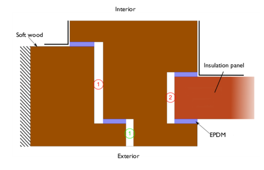
Figure 3 and Figure 4 depict the geometry of each application but only a part of the insulation panel or glazing is represented. Unventilated cavities are red-numbered while slightly ventilated cavities are green-numbered. Boundaries with an increased thermal resistance are represented with bold black lines. Adiabatic boundaries in contact with the wall are represented with a striped rectangle.
Application 1: Wood Frame with an Insulation Panel
The first application studies the heat conduction in the wood frame section with an insulation panel. The frame section is made of two wood blocks with a low thermal conductivity of 0.13 W/(m·K). In order to make the contact between these two blocks and to waterproof the window, two ethylene propylene diene monomer (EPDM) gaskets are used. Two other EPDM blocks are arranged on both sides of the insulation panel. The insulation panel has a very low thermal conductivity of 0.035 W/(m·K).
Two cavities are completely closed and are considered as unventilated. The third one is considered as slightly ventilated.
Figure 3: Geometry of the wood frame with an insulation panel.
Application 2: Wood Frame with a Traditional Glazing
The glazing is made of two glass panels with a thermal conductivity of 1.00 W/(m·K). On the frame side of the glazing, a structure made of aluminum, polysulfide, and silica gel is used to block the glass blocks. Their thermal conductivities are 160 W/(m·K), 0.40 W/(m·K), and 0.13 W/(m·K), respectively. The space between the glass panels is filled with a gas whose thermal conductivity is 0.034 W/(m·K) (so this space is not considered as a traditional air cavity).
Figure 4: Geometry of the wood frame with a glazing.
Results and Discussion
Temperature profiles
Figure 5 and Figure 6 show the temperature profiles for each application.
Figure 5: Temperature profile with the insulation panel.
Figure 6: Temperature distribution with glazing.
Quantities of interest
The quantities of interest are the following:
where is the heat flow rate through the window (in W/m), Te = 0°C is the external temperature and Ti = 20°C is the internal temperature.
where bp is the visible width of the panel expressed in meters, bf is the projected width of the frame section expressed in meters and Up is the thermal transmittance of the central area of the panel expressed in W/(m2·K).
where bg is the visible width of the glazing expressed in meters, Ug is the thermal transmittance of the central area of the glazing expressed in W/(m2·K).
Here, Ψ describes the additional heat flow caused by the interaction of the frame and the glass edge, including the effect of the spacer. The thermal transmittance Ug is provided, equal to 1.3 W/(m2·K).
Table 1 and Table 2 compare the numerical results of COMSOL Multiphysics with the expected values provided by ISO 10077-2:2012.
Table 1: comparison between expected and computed values of quantities in Application 1.
L2D (W/(m·K))
Uf (W/(m2·K))
Table 2: comparison between expected and computed values of quantities in Application 2.
L2D (W/(m·K))
Ψ (W/(m2·K))
The maximum permissible differences to pass this test case are 3% for the thermal conductance and 5% for the (linear) thermal transmittance. The measured values are completely coherent and meet the validation criteria.
Reference
1. European Committee for Standardization, ISO 10077-2:2012, Thermal performance of windows, doors and shutters – Calculation of thermal transmittance – Part 2: Numerical method for frames, 2012.
Application Library path: Heat_Transfer_Module/Buildings_and_Constructions/window_and_glazing_thermal_performances
Modeling Instructions
Root
Start by opening the following prepared file. It already contains global definitions, geometries, local variables, selections, operators and material properties.
1
From the File menu, choose Open.
2
Window with Insulation Panel
Window with Insulation Panel (comp1)
In the Model Builder window, expand the Window with Insulation Panel (comp1) node.
Definitions (comp1)
Variables 1
Define the thermal conductance of the section for the postprocessing part as follows.
1
In the Model Builder window, expand the Window with Insulation Panel (comp1)>Definitions node, then click Variables 1.
2
In the Settings window for Variables, locate the Variables section.
3
Note that the heat flow rate through the internal and through the external boundaries are equal (in absolute value) because other boundaries are considered adiabatic.
4
In the Model Builder window, collapse the Window with Insulation Panel (comp1)>Definitions node.
Heat Transfer in Solids and Fluids (ht)
Fluid 1
1
In the Model Builder window, expand the Heat Transfer in Solids and Fluids (ht) node, then click Fluid 1.
2
As there is no convection, a second order discretization of the temperature is set for better accuracy.
3
In the Model Builder window, click Heat Transfer in Solids and Fluids (ht).
4
In the Settings window for Heat Transfer in Solids and Fluids, click to expand the Discretization section.
5
From the Temperature list, choose Quadratic Lagrange.
Heat Flux 1
1
In the Physics toolbar, click  Boundaries and choose Heat Flux.
2
In the Settings window for Heat Flux, locate the Boundary Selection section.
3
From the Selection list, choose Exterior Side.
4
Locate the Heat Flux section. Click the Convective heat flux button.
5
In the h text field, type 1/Rse.
6
In the Text text field, type Te.
Heat Flux 2
1
In the Physics toolbar, click  Boundaries and choose Heat Flux.
2
In the Settings window for Heat Flux, locate the Boundary Selection section.
3
From the Selection list, choose Interior Side (Flat Area).
4
Locate the Heat Flux section. Click the Convective heat flux button.
5
In the h text field, type 1/Rsi_n.
6
In the Text text field, type Ti.
Heat Flux 3
1
In the Physics toolbar, click  Boundaries and choose Heat Flux.
2
In the Settings window for Heat Flux, locate the Boundary Selection section.
3
From the Selection list, choose Interior Side (Corner Area).
4
Locate the Heat Flux section. Click the Convective heat flux button.
5
In the h text field, type 1/Rsi_p.
6
In the Text text field, type Ti.
Open Boundary 1
1
In the Physics toolbar, click  Boundaries and choose Open Boundary.
2
3
In the Settings window for Open Boundary, locate the Upstream Properties section.
4
In the Tustr text field, type Te.
5
In the Model Builder window, collapse the Heat Transfer in Solids and Fluids (ht) node.
Study 1
The heat flow rate through the interior (or exterior) side of the section needs to be determined to calculate the thermal conductance of the section. In order to have enough precision in this value, the default relative tolerance of the solver has already been modified to 106. To access to this value, expand the Solver 1 node and click on the Stationary Solver 1 node. In the Stationary Solver settings window, locate the General section.
1
In the Home toolbar, click  Compute.
Results
Temperature (ht)
A Global Evaluation node is added in order to calculate the thermal conductance of the section and the thermal transmittance of the frame.
Thermal Properties, Window with Insulation Panel
1
In the Model Builder window, expand the Results>Derived Values node.
2
Right-click Derived Values and choose Global Evaluation.
3
In the Settings window for Global Evaluation, type Thermal Properties, Window with Insulation Panel in the Label text field.
4
Locate the Expressions section. In the table, enter the following settings:
5
Click  Evaluate.
Table
1
Go to the Table window.
The results should be close to the expected values in Table 1.
Results
Surface
1
In the Model Builder window, expand the Results>Temperature (ht) node, then click Surface.
2
In the Settings window for Surface, locate the Expression section.
3
From the Unit list, choose degC.
4
In the Temperature (ht) toolbar, click  Plot.
The current plot group shows the temperature distribution; compare with Figure 5.
The same simulation method is applied to the other benchmark. The instructions below describe the steps to achieve the calculations.
Window with Insulation Panel (comp1)
In the Model Builder window, collapse the Window with Insulation Panel (comp1) node.
Window with Glazing
Window with Glazing (comp2)
In the Model Builder window, expand the Window with Glazing (comp2) node.
Definitions (comp2)
Variables 2
1
In the Model Builder window, expand the Window with Glazing (comp2)>Definitions node, then click Variables 2.
2
In the Settings window for Variables, locate the Variables section.
3
4
In the Model Builder window, collapse the Window with Glazing (comp2)>Definitions node.
Heat Transfer in Solids and Fluids 2 (ht2)
Fluid 1
1
In the Model Builder window, expand the Heat Transfer in Solids and Fluids 2 (ht2) node, then click Fluid 1.
2
As there is no convection, a second order discretization of the temperature is set for better accuracy.
3
In the Model Builder window, click Heat Transfer in Solids and Fluids 2 (ht2).
4
In the Settings window for Heat Transfer in Solids and Fluids, click to expand the Discretization section.
5
From the Temperature list, choose Quadratic Lagrange.
Heat Flux 1
1
In the Physics toolbar, click  Boundaries and choose Heat Flux.
2
In the Settings window for Heat Flux, locate the Boundary Selection section.
3
From the Selection list, choose Exterior Side.
4
Locate the Heat Flux section. Click the Convective heat flux button.
5
In the h text field, type 1/Rse.
6
In the Text text field, type Te.
Heat Flux 2
1
In the Physics toolbar, click  Boundaries and choose Heat Flux.
2
In the Settings window for Heat Flux, locate the Boundary Selection section.
3
From the Selection list, choose Interior Side (Flat Area).
4
Locate the Heat Flux section. Click the Convective heat flux button.
5
In the h text field, type 1/Rsi_n.
6
In the Text text field, type Ti.
Heat Flux 3
1
In the Physics toolbar, click  Boundaries and choose Heat Flux.
2
In the Settings window for Heat Flux, locate the Boundary Selection section.
3
From the Selection list, choose Interior Side (Corner Area).
4
Locate the Heat Flux section. Click the Convective heat flux button.
5
In the h text field, type 1/Rsi_p.
6
In the Text text field, type Ti.
Open Boundary 1
1
In the Physics toolbar, click  Boundaries and choose Open Boundary.
2
3
In the Settings window for Open Boundary, locate the Upstream Properties section.
4
In the Tustr text field, type Te.
5
In the Model Builder window, collapse the Heat Transfer in Solids and Fluids 2 (ht2) node.
Study 2
In the Home toolbar, click  Compute.
Results
A Global Evaluation node is added in order to calculate the thermal conductance of the section and the linear thermal transmittance of the frame.
Thermal Properties, Window with Glazing
1
In the Results toolbar, click  Global Evaluation.
2
In the Settings window for Global Evaluation, type Thermal Properties, Window with Glazing in the Label text field.
3
Locate the Data section. From the Dataset list, choose Study 2/Solution 2 (4) (sol2).
4
Locate the Expressions section. In the table, enter the following settings:
5
Click  Evaluate.
Table
1
Go to the Table window.
The results should be close to the expected values in Table 2.
Results
Surface
1
In the Model Builder window, expand the Results>Temperature (ht2) node, then click Surface.
2
In the Settings window for Surface, locate the Expression section.
3
From the Unit list, choose degC.
4
In the Temperature (ht2) toolbar, click  Plot.
The current plot group shows the temperature distribution; compare with Figure 6.