The resulting value of Zi can be treated as a superposition of several contributions which are derived separately. Note that the theory below is only valid for the perforates with circular-shaped holes. Other types of holes can lead to significantly different results, which will make the models that are considered here inadequate and unreliable.
Let the z-coordinate axis be directed along the axis of a cylindrical hole of the height
tp (see
Figure 2-14). Let the variation of the pressure and the velocity along the
z-axis have the following pattern:
where Zc is the characteristic impedance and
kc is the complex wave number defined according to the low reduced frequency (LRF) models from the
Narrow Region Acoustics for
Slits, Circular Ducts, Rectangular Ducts, and Equilateral triangular Ducts. That is,
Note that Equation 2-35 coincides with the expression that follows from Crandall’s formula for an infinite tube with the circular cross section (see
Ref. 35).
Equation 2-34 accounts for both viscous and thermal effects inside the hole, while the simplified
Equation 2-35 contains the viscous part only (thermal effects are negligible for the thin plate limit).
Equation 2-34 and
Equation 2-35 are exact if the streamlines of a flow through the hole are parallel to the
z-axis throughout the orifice area. In reality, there is a radial component of the flow, which leads to the reduction (contraction) of this area. The minimum area where the streamlines remain parallel to the
z-axis is called
vena contracta. The flow velocity at the vena contracta is also different from that of the ideal flow. A coefficient that accounts for these effects is called the discharge coefficient,
CD. The value of the discharge coefficient can be obtained from measurements as function of the plate thickness and the orifice shape and diameter.
Another parameter that used to express the interior impedance of a perforate is the porosity, σ. The holes are usually uniformly distributed over the plate, and the porosity accounts for the distribution as the ratio of the hollow area to the area of the plate. Depending on the pattern used when the holes are strewn over the plate, the porosity is defined as follows
Either Equation 2-34 or
Equation 2-35 can be used for the substitution for
zi in
Equation 2-36. The resulting models will further be referred to as the thick and the thin plate models, respectively.
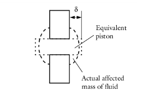
The subscript “orifice” in Equation 2-36 means that the expression accounts for the transfer impedance of a perforate caused by the presence of the holes; that is, a piston of fluid of the length
tp. However, the actual mass of fluid affected by an incident wave is larger than that inside the hole. The effective mass of the fluid can be taken into account by the piston which is on each side longer by
δ than the initial one (see
Figure 2-15). This results in adding two extra terms (for each side of the perforate) of the form
Equation 2-35 with
tp replaced by
δ. The choice of
Equation 2-35 is due to the absence of highly conducting walls in the end corrections area.
correction is reduced by a factor fint. The last is a function of the porosity and the most often expressed by the Fok function:
where fnl is a correction factor (equals
1 by default) and
vn is the acoustic particle velocity component normal to the plate. Other expressions for the nonlinear resistance term can be found in
Ref. 36.
Combining the expressions Equation 2-36–
Equation 2-39 together yields the full expression for the transfer impedance of a perforate for the thick
plate models. The discharge coefficient CD is taken different for the linear and the nonlinear parts for the sake of flexibility.

 .
.
 ,
,

 .
. .
.