Slot Joint Theory
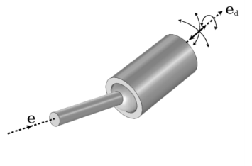
The Slot Joint has three rotational and one translational degrees of freedom between the two attached components. The components are free to rotate relative to each other about all three axes and also free to translate along the joint translation axis. The slot joint can be seen as a combination of the prismatic joint and the ball joint.
The following is an addition to the Prismatic Joint Theory and the Ball Joint Theory, which are also applicable to the slot joint.
Slot Joint Axis and its Local Coordinate System
For a slot joint, the translational motion is free along the joint translational axis, which can be either the source axis or the destination axis. The translational degrees of freedom is added along the joint translational axis.
You can specify the initial joint translational axis (etr0) to be either
or
For the slot joint, the process of defining the source axis, destination axis, and local coordinate system is the same as for the ball joint.
The joint coordinate system is always attached to the source part even if the joint translational axis is defined by the destination axis.
Slot Joint Formulation
The slot joint formulation is similar to the ball joint except that an extra translational degree of freedom is needed. The joint translational axis is used for the relative displacement vector, and the rotational degrees of freedom are represented by a relative quaternion as in the ball joint.
Joint Elasticity in Slot Joint
The elastic degrees of freedom depends on whether the joint translational axis is defined to be the source axis or the destination axis. In both cases, there are two constrained translations, but it is only when the source axis is the joint translational axis that the elastic displacement can be expressed in the joint coordinate system direction
When the joint translational axis is the destination axis, then
where ed2 and ed3 are second and third axis of the destination coordinate system, respectively. In this case, the stiffness and damping matrices are given along the destination axes when the joint coordinate system is selected.
Except for this difference, the formulation is the same as for the ball joint.