Ball Joint Theory
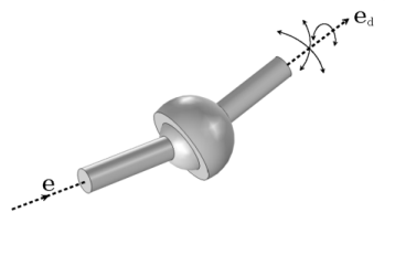
The Ball Joint, also known as a spherical joint, has three rotational degrees of freedom between the two attached components. The two components are free to rotate relative to each other along all three axes.
The following is an addition to the Hinge Joint Theory, some of which is also applicable to the ball joint.
Ball Joint Axis and its Local Coordinate System
Unlike other joints, the ball joint has no particular axis about which the relative degrees of freedom between the two components are possible. This joint has rotational symmetry, and hence, relative rotation is allowed about any axis. However, application of constraints, springs, dampers, and so forth needs the source (e1) and destination (ed1) axes. The local coordinate system of this joint is defined using the source axis.
You specify the initial source axis (e10) and initial destination axis (ed10) in terms of components along the axes of the selected coordinate system. The initial source axis must point toward the center of joint, whereas the initial destination axis must point away from the center of joint.
The process of creating a rotated source axis, rotated destination axis, and a corresponding local coordinate system is the same as for the hinge joint. The auxiliary axis is taken as the initial destination axis unless it is parallel to the initial source axis.
Ball Joint Formulation
For a ball joint, the destination attachment is free to rotate relative to the source attachment about all three axes. The added degrees of freedom are contained in a relative quaternion (a, b, c, and d), which represents the rotation in 3D. The rest of the formulation is similar to that of the hinge joint.
Joint Elasticity in Ball Joint
Since only translations are constrained in a ball joint, the elastic degrees of freedom are
Therefore, there are only elastic forces and no elastic moments or coupling matrices.
The total elastic joint forces can be written using the spring and damping forces as
The contribution to the virtual work is