|
|
|


|
1
|
|
2
|
In the Select Physics tree, select Optics > Wave Optics > Electromagnetic Waves, Frequency Domain (ewfd).
|
|
3
|
Click Add.
|
|
4
|
Click
|
|
5
|
In the Select Study tree, select Preset Studies for Selected Physics Interfaces > Wavelength Domain.
|
|
6
|
Click
|
|
1
|
|
2
|
|
1
|
|
2
|
|
3
|
|
1
|
|
2
|
|
3
|
|
4
|
|
5
|
|
6
|
Click to expand the Layers section. In the table, enter the following settings:
|
|
7
|
Click
|
|
8
|
|
9
|
|
1
|
In the Model Builder window, under Component 1 (comp1) right-click Materials and choose Blank Material.
|
|
2
|
|
4
|
Locate the Material Contents section. In the table, enter the following settings:
|
|
1
|
|
2
|
|
4
|
Locate the Material Contents section. In the table, enter the following settings:
|
|
1
|
In the Model Builder window, under Component 1 (comp1) click Electromagnetic Waves, Frequency Domain (ewfd).
|
|
2
|
In the Settings window for Electromagnetic Waves, Frequency Domain, type Electromagnetic Waves, Frequency Domain (ewfd, TE) in the Label text field.
|
|
1
|
|
2
|
|
3
|
|
1
|
|
2
|
|
1
|
|
2
|
|
3
|
|
4
|
|
5
|
Click
|
|
1
|
|
1
|
|
2
|
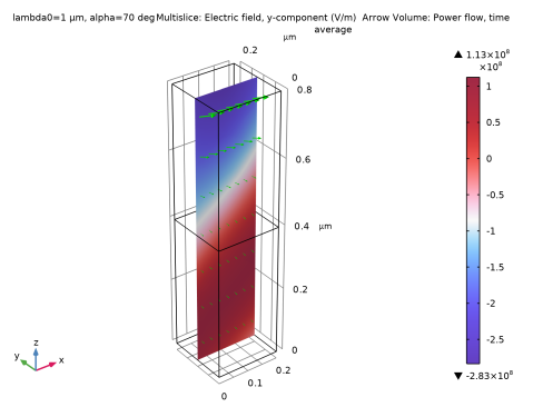
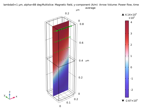
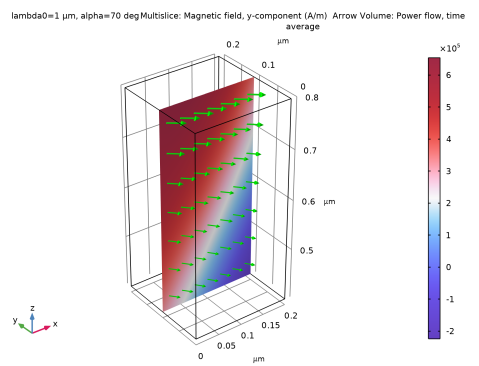
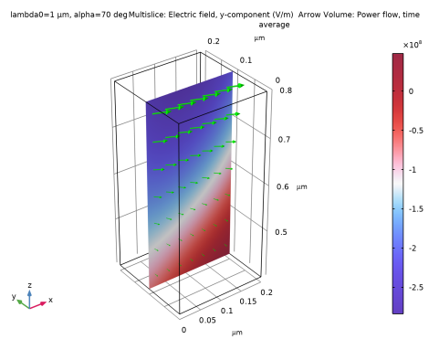
In the Settings window for Multislice, click Replace Expression in the upper-right corner of the Expression section. From the menu, choose Component 1 (comp1) > Electromagnetic Waves, Frequency Domain (ewfd, TE) > Electric > Electric field - V/m > ewfd.Ey - Electric field, y-component.
|
|
3
|
|
4
|
|
5
|
|
1
|
|
2
|
In the Settings window for Arrow Volume, click Replace Expression in the upper-right corner of the Expression section. From the menu, choose Component 1 (comp1) > Electromagnetic Waves, Frequency Domain (ewfd, TE) > Energy and power > ewfd.Poavx,...,ewfd.Poavz - Power flow, time average.
|
|
3
|
Locate the Arrow Positioning section. Find the Y grid points subsection. In the Points text field, type 1.
|
|
4
|
|
1
|
|
2
|
|
3
|
|
4
|
|
5
|
|
1
|
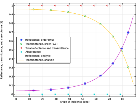
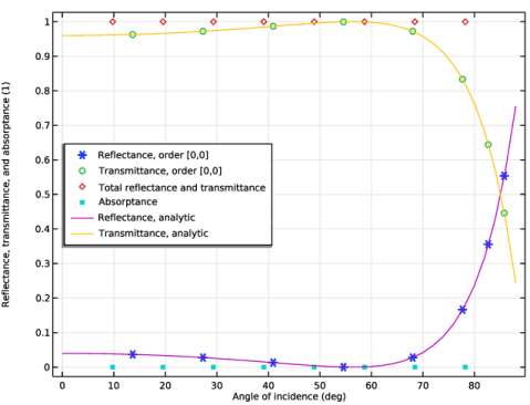
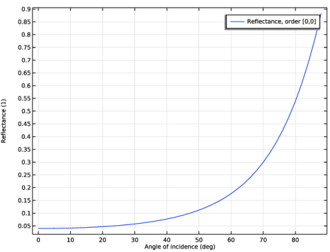
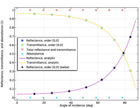
In the Model Builder window, under Results click Reflectance, Transmittance, and Absorptance (ewfd).
|
|
2
|
In the Settings window for 1D Plot Group, type Reflectance, Transmittance, and Absorptance (ewfd, TE) in the Label text field.
|
|
3
|
|
4
|
|
5
|
|
1
|
In the Model Builder window, expand the Reflectance, Transmittance, and Absorptance (ewfd, TE) node, then click Global 1.
|
|
2
|
|
3
|
|
4
|
|
5
|
|
1
|
In the Model Builder window, right-click Reflectance, Transmittance, and Absorptance (ewfd, TE) and choose Global.
|
|
2
|
|
4
|
|
5
|
|
7
|
|
1
|
|
2
|
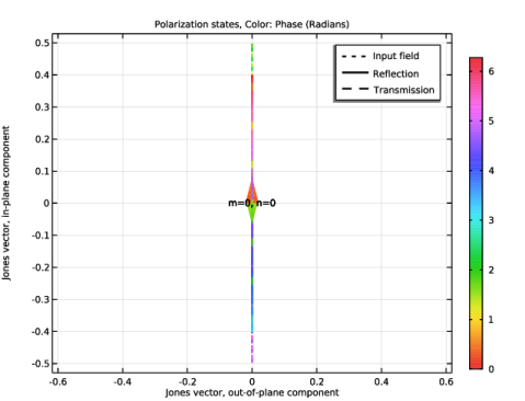
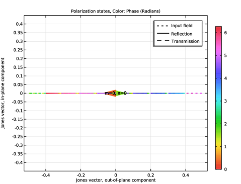
In the Settings window for 1D Plot Group, type Polarization Plot (ewfd, TE) in the Label text field.
|
|
3
|
|
1
|
In the Model Builder window, right-click Component 1 (comp1) and choose Paste Electromagnetic Waves, Frequency Domain.
|
|
2
|
|
3
|
In the Settings window for Electromagnetic Waves, Frequency Domain, type Electromagnetic Waves, Frequency Domain (ewfd2, TM) in the Label text field.
|
|
1
|
In the Model Builder window, expand the Component 1 (comp1) > Electromagnetic Waves, Frequency Domain (ewfd2, TM) (ewfd2) node, then click Periodic Structure 1.
|
|
2
|
|
3
|
From the list, choose P. This will change the port mode fields to be polarized parallel to the plane of incidence.
|
|
1
|
|
2
|
Go to the Add Study window.
|
|
3
|
|
4
|
Click the Add Study button in the window toolbar.
|
|
5
|
|
1
|
|
2
|
In the Solve for column of the table, under Component 1 (comp1), clear the checkbox for Electromagnetic Waves, Frequency Domain (ewfd, TE) (ewfd).
|
|
3
|
|
1
|
|
2
|
|
3
|
|
4
|
|
5
|
|
6
|
|
1
|
|
2
|
|
3
|
|
4
|
|
5
|
|
6
|
Locate the Arrow Positioning section. Find the Y grid points subsection. In the Points text field, type 1.
|
|
7
|
|
8
|
|
1
|
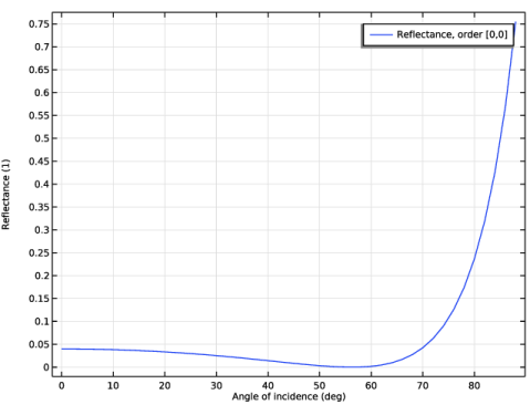
In the Model Builder window, under Results click Reflectance, Transmittance, and Absorptance (ewfd2).
|
|
2
|
In the Settings window for 1D Plot Group, type Reflectance, Transmittance, and Absorptance (ewfd2, TM) in the Label text field.
|
|
3
|
|
4
|
|
5
|
|
1
|
In the Model Builder window, expand the Reflectance, Transmittance, and Absorptance (ewfd2, TM) node, then click Global 1.
|
|
2
|
|
3
|
|
4
|
|
5
|
|
1
|
In the Model Builder window, right-click Reflectance, Transmittance, and Absorptance (ewfd2, TM) and choose Global.
|
|
2
|
|
4
|
|
6
|
|
7
|
|
1
|
|
2
|
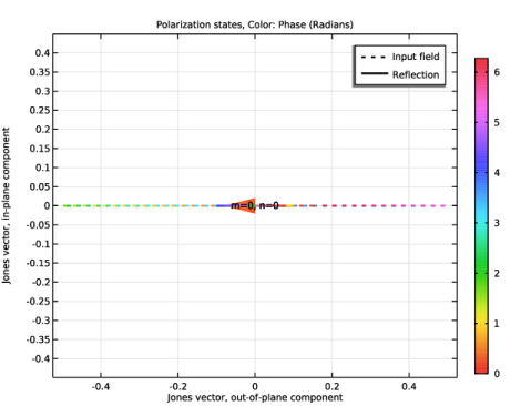
In the Settings window for 1D Plot Group, type Polarization Plot (ewfd2, TM) in the Label text field.
|
|
3
|
|
1
|
|
2
|
Go to the Add Physics window.
|
|
3
|
|
4
|
Click the Add to Component 1 button in the window toolbar.
|
|
5
|
|
1
|
In the Settings window for Electromagnetic Waves, Beam Envelopes, type Electromagnetic Waves, Beam Envelopes (ewbe, TE) in the Label text field.
|
|
3
|
|
4
|
|
1
|
|
3
|
|
4
|
|
5
|
Locate the Port Mode Settings section. From the Polarization list, choose Linear polarization, to give a polarization in the y-direction (orthogonal to the plane of incidence).
|
|
6
|
|
1
|
|
3
|
|
4
|
|
5
|
|
1
|
|
3
|
|
4
|
|
5
|
|
1
|
|
3
|
|
4
|
From the list, choose From wave vector, to make the Impedance Boundary Condition also work for nonnormal propagation in the exterior (glass) material.
|
|
1
|
In the Model Builder window, under Component 1 (comp1) > Materials right-click Glass (mat2) and choose Duplicate.
|
|
2
|
|
3
|
Locate the Geometric Entity Selection section. From the Geometric entity level list, choose Boundary.
|
|
1
|
|
2
|
|
3
|
|
1
|
|
2
|
|
3
|
In the table, clear the Use checkboxes for Electromagnetic Waves, Frequency Domain (ewfd, TE) (ewfd) and Electromagnetic Waves, Frequency Domain (ewfd2, TM) (ewfd2).
|
|
4
|
Locate the Electromagnetic Waves, Beam Envelopes (ewbe, TE) (ewbe) section. In the NT text field, type 1.
|
|
5
|
|
6
|
|
1
|
|
2
|
Go to the Add Study window.
|
|
3
|
|
4
|
Click the Add Study button in the window toolbar.
|
|
1
|
|
2
|
In the Solve for column of the table, under Component 1 (comp1), clear the checkbox for Electromagnetic Waves, Frequency Domain (ewfd2, TM) (ewfd2).
|
|
3
|
Click to expand the Mesh Selection section. In the table, enter the following settings:
|
|
4
|
|
5
|
|
1
|
|
2
|
|
1
|
|
2
|
|
3
|
|
4
|
|
5
|
|
6
|
|
1
|
|
2
|
In the Settings window for Arrow Volume, click Replace Expression in the upper-right corner of the Expression section. From the menu, choose Component 1 (comp1) > Electromagnetic Waves, Beam Envelopes (ewbe, TE) > Energy and power > ewbe.Poavx,...,ewbe.Poavz - Power flow, time average.
|
|
3
|
Locate the Arrow Positioning section. Find the Y grid points subsection. In the Points text field, type 1.
|
|
4
|
|
5
|
|
1
|
|
1
|
In the Model Builder window, under Results > Reflectance, Transmittance, and Absorptance (ewfd, TE) right-click Global 1 and choose Duplicate.
|
|
2
|
|
3
|
|
4
|
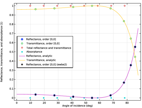
Click Replace Expression in the upper-right corner of the y-Axis Data section. From the menu, choose Component 1 (comp1) > Electromagnetic Waves, Beam Envelopes (ewbe, TE) > Ports > Reflectance, by order > ewbe.Rorder_0_0 - Reflectance, order [0,0].
|
|
5
|
Locate the y-Axis Data section. In the table, enter the following settings:
|
|
6
|
|
1
|
|
2
|
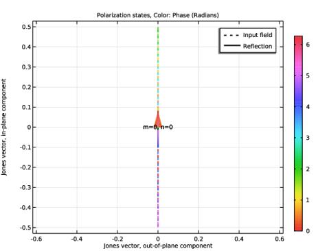
In the Settings window for 1D Plot Group, type Polarization Plot (ewbe, TE) in the Label text field.
 |
|
1
|
In the Model Builder window, right-click Component 1 (comp1) and choose Paste Electromagnetic Waves, Beam Envelopes.
|
|
2
|
|
3
|
In the Settings window for Electromagnetic Waves, Beam Envelopes, type Electromagnetic Waves, Beam Envelopes (ewbe2, TM) in the Label text field.
|
|
1
|
In the Model Builder window, expand the Component 1 (comp1) > Electromagnetic Waves, Beam Envelopes (ewbe2, TM) (ewbe2) node, then click Port 1.
|
|
2
|
|
3
|
From the list, choose P, to give a polarization that is parallel to the plane of incidence.
|
|
1
|
|
2
|
Go to the Add Study window.
|
|
3
|
|
4
|
Click the Add Study button in the window toolbar.
|
|
5
|
|
1
|
|
2
|
In the Solve for column of the table, under Component 1 (comp1), clear the checkbox for Electromagnetic Waves, Beam Envelopes (ewbe, TE) (ewbe).
|
|
3
|
|
1
|
|
2
|
|
1
|
|
2
|
|
3
|
|
4
|
|
5
|
|
6
|
|
1
|
|
2
|
In the Settings window for Arrow Volume, click Replace Expression in the upper-right corner of the Expression section. From the menu, choose Component 1 (comp1) > Electromagnetic Waves, Beam Envelopes (ewbe2, TM) > Energy and power > ewbe2.Poavx,...,ewbe2.Poavz - Power flow, time average.
|
|
3
|
Locate the Arrow Positioning section. Find the Y grid points subsection. In the Points text field, type 1.
|
|
4
|
|
5
|
|
1
|
|
2
|
|
1
|
In the Model Builder window, under Results > Reflectance, Transmittance, and Absorptance (ewfd2, TM) right-click Global 1 and choose Duplicate.
|
|
2
|
|
3
|
|
4
|
Click Replace Expression in the upper-right corner of the y-Axis Data section. From the menu, choose Component 1 (comp1) > Electromagnetic Waves, Beam Envelopes (ewbe2, TM) > Ports > Reflectance, by order > ewbe2.Rorder_0_0 - Reflectance, order [0,0].
|
|
5
|
Locate the y-Axis Data section. In the table, enter the following settings:
|
|
6
|
|
1
|
|
2
|
In the Settings window for 1D Plot Group, type Polarization Plot (ewbe2, TM) in the Label text field.
 |