
|
|
|
 |
||
 |
||
 |
||
|
1
|
|
2
|
|
3
|
Click Add.
|
|
4
|
Click
 Study. Study. |
|
5
|
|
6
|
Click
 Done. Done. |
|
1
|
|
2
|
|
3
|
Click
 Load from File. Load from File. |
|
4
|
Browse to the model’s Application Libraries folder and double-click the file hubble_space_telescope_parameters.txt.
|
|
1
|
|
2
|
|
3
|
In the Part Libraries window, select Ray Optics Module > 3D > Mirrors > conic_mirror_on_axis_3d in the tree.
|
|
4
|
Click
 Add to Geometry. Add to Geometry. |
|
5
|
In the Select Part Variant dialog, select Specify clear aperture diameter in the Select part variant list.
|
|
6
|
Click OK.
|
|
1
|
In the Model Builder window, under Component 1 (comp1) > Geometry 1 click Conic Mirror On Axis 3D 1 (pi1).
|
|
2
|
|
3
|
Locate the Input Parameters section. In the table, enter the following settings:
|
|
4
|
Locate the Position and Orientation of Output section. Find the Displacement subsection. In the zwi text field, type Z_prim.
|
|
5
|
Click
 Build Selected. Build Selected. |
|
6
|
Click to expand the Boundary Selections section. In the table, select the Keep checkbox for Mirror surface.
|
|
8
|
Click New Cumulative Selection.
|
|
9
|
|
10
|
Click OK.
|
|
11
|
|
1
|
|
2
|
|
3
|
Locate the Input Parameters section. In the table, enter the following settings:
|
|
4
|
Locate the Position and Orientation of Output section. Find the Coordinate system to match subsection. From the Take work plane from list, choose Primary Mirror (pi1).
|
|
5
|
|
6
|
|
7
|
Click
 Build Selected. Build Selected. |
|
8
|
Locate the Boundary Selections section. In the table, enter the following settings:
|
|
1
|
|
2
|
|
3
|
Locate the Parameters section. Find the First parameter subsection. In the Minimum text field, type -hw_image.
|
|
4
|
|
5
|
|
6
|
|
7
|
|
8
|
|
9
|
In the z text field, type Cp*(s1^2 + s2^2)/(1 + sqrt(1 - Cp^2*(s1^2 + s2^2)))*1[m]. This is the equation of a sphere having a curvature Cp. This is the Petzval curvature defined in the Parameters node.
|
|
10
|
|
11
|
Locate the Coordinate System section. From the Take work plane from list, choose Secondary Mirror (pi2).
|
|
12
|
|
13
|
Locate the Selections of Resulting Entities section. Select the Resulting objects selection checkbox.
|
|
1
|
|
2
|
|
3
|
In the Part Libraries window, select Ray Optics Module > 3D > Apertures and Obstructions > circular_planar_annulus in the tree.
|
|
4
|
Click
 Add to Geometry. Add to Geometry. |
|
1
|
In the Model Builder window, under Component 1 (comp1) > Geometry 1 click Circular Planar Annulus 1 (pi3).
|
|
2
|
|
3
|
Locate the Input Parameters section. In the table, enter the following settings:
|
|
4
|
Locate the Position and Orientation of Output section. Find the Coordinate system to match subsection. From the Take work plane from list, choose Secondary Mirror (pi2).
|
|
5
|
|
6
|
|
7
|
Locate the Boundary Selections section. In the table, enter the following settings:
|
|
8
|
Click
 Build Selected. Build Selected. |
|
9
|
|
10
|
|
11
|
|
1
|
|
2
|
|
3
|
Click
 Clear Selection. Clear Selection. |
|
4
|
Locate the Ray Release and Propagation section. In the Maximum number of secondary rays text field, type 0.
|
|
1
|
|
2
|
|
3
|
Locate the Boundary Selection section. From the Selection list, choose Mirror surface (Primary Mirror).
|
|
1
|
|
2
|
|
3
|
Locate the Boundary Selection section. From the Selection list, choose Mirror surface (Secondary Mirror).
|
|
1
|
|
2
|
|
3
|
|
4
|
|
1
|
|
2
|
|
3
|
|
1
|
|
2
|
|
3
|
|
4
|
|
5
|
|
6
|
|
7
|
|
8
|
|
1
|
|
2
|
|
3
|
|
4
|
|
1
|
|
2
|
|
3
|
|
4
|
|
1
|
|
2
|
|
3
|
|
4
|
In the Lengths text field, type 0 17. This path length is sufficient to ensure that all rays reach the image plane.
|
|
5
|
|
1
|
|
2
|
|
3
|
|
4
|
Select the Show units checkbox.
|
|
5
|
|
1
|
In the Model Builder window, expand the Results > Ray Diagram > Ray Trajectories 1 node, then click Color Expression 1.
|
|
2
|
|
3
|
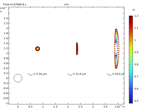
In the Expression text field, type at('last',gop.rrel). This is the radial coordinate relative to the centroid at the image plane for each release feature.
|
|
4
|
|
1
|
|
2
|
|
3
|
|
4
|
|
1
|
|
2
|
|
3
|
|
1
|
|
2
|
|
3
|
|
4
|
|
5
|
|
6
|
Click Define custom colors.
|
|
8
|
Click Add to custom colors.
|
|
9
|
|
1
|
|
3
|
|
1
|
|
2
|
|
3
|
|
1
|
|
2
|
|
3
|
|
4
|
|
5
|
|
6
|
|
1
|
|
2
|
|
3
|
In the Expression text field, type at(0,gop.rrel). This is the radial coordinate relative to the centroid at the entrance pupil for each ray release.
|
|
4
|


