| 
|
|
|
|
|
1
|
|
2
|
|
3
|
Click Add.
|
|
4
|
Click
|
|
5
|
|
6
|
Click
|
|
1
|
|
2
|
|
3
|
Click
|
|
4
|
|
1
|
|
2
|
|
3
|
|
4
|
|
5
|
|
6
|
|
7
|
Click
|
|
1
|
|
2
|
|
3
|
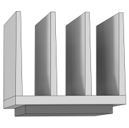
In the Part Libraries window, select Heat Transfer Module > Heat Sinks > heat_sink_straight_fins in the tree.
|
|
4
|
Click
|
|
1
|
In the Model Builder window, under Component 1 (comp1) > Geometry 1 click Heat Sink - Straight Fins 1 (pi1).
|
|
2
|
|
4
|
Locate the Position and Orientation of Output section. Find the Coordinate system in part subsection. From the Work plane in part list, choose Work plane for heat sink base (wp11).
|
|
5
|
|
6
|
|
7
|
Click to expand the Domain Selections section. In the table, enter the following settings:
|
|
8
|
Click to collapse the Domain Selections section. Click to expand the Boundary Selections section. In the table, enter the following settings:
|
|
9
|
|
10
|
|
11
|
|
1
|
|
2
|
Go to the Add Material window.
|
|
3
|
|
4
|
Right-click and choose Add to Component 1 (comp1).
|
|
5
|
|
6
|
Right-click and choose Add to Component 1 (comp1).
|
|
7
|
|
1
|
|
2
|
|
4
|
|
5
|
Click
|
|
6
|
|
7
|
Click OK.
|
|
1
|
|
2
|
|
3
|
|
4
|
|
5
|
|
1
|
|
2
|
|
3
|
From the Selection list, choose Exterior boundaries without heat sink base (Heat Sink - Straight Fins 1).
|
|
4
|
|
5
|
|
6
|
|
7
|
|
1
|
|
2
|
|
3
|
Click
|
|
4
|
|
5
|
Click OK.
|
|
6
|
|
8
|
Click
|
|
1
|
|
2
|
|
3
|
|
4
|
|
1
|
|
2
|
|
3
|
|
1
|
|
2
|
|
3
|
|
4
|
|
1
|
|
2
|
|
3
|
|
4
|
|
1
|
|
2
|
|
1
|
|
3
|
|
4
|
Click
|
|
5
|
|
6
|
Click OK.
|
|
7
|
|
8
|
|
9
|
|
10
|
|
1
|
|
2
|
Go to the Add Material window.
|
|
3
|
|
4
|
Right-click and choose Add to Component 1 (comp1).
|
|
5
|
|
1
|
|
2
|
|
3
|
|
4
|
|
1
|
|
2
|
Go to the Add Material window.
|
|
3
|
|
4
|
Right-click and choose Add to Component 1 (comp1).
|
|
5
|
|
1
|
|
2
|
|
3
|
|
4
|
|
1
|
|
2
|
|
3
|
|
4
|
|
5
|
|
6
|
|
7
|
|
8
|
|
9
|
|
1
|
In the Model Builder window, under Component 1 (comp1) > Materials right-click Air (mat3) and choose Duplicate.
|
|
2
|
|
3
|
|
5
|
Click
|
|
6
|
|
7
|
Click OK.
|
|
1
|
|
2
|
Go to the Add Physics window.
|
|
3
|
|
4
|
Click the Add to Component 1 button in the window toolbar.
|
|
5
|
|
1
|
|
2
|
|
1
|
|
3
|
|
4
|
Click
|
|
5
|
|
6
|
Click OK.
|
|
7
|
|
8
|
From the list, choose Fully developed flow.
|
|
9
|
|
1
|
|
3
|
|
4
|
Click
|
|
5
|
|
6
|
Click OK.
|
|
1
|
|
2
|
|
3
|
|
1
|
|
2
|
|
3
|
|
4
|
|
1
|
|
2
|
|
3
|
|
1
|
|
2
|
Go to the Add Multiphysics window.
|
|
3
|
|
4
|
Click the Add to Component button in the window toolbar.
|
|
5
|
|
1
|
|
2
|
|
3
|
|
4
|
|
1
|
|
2
|
Go to the Result Templates window.
|
|
3
|
In the tree, select Study 1/Solution 1 (sol1) > Nonisothermal Flow 1 > Temperature and Fluid Flow (nitf1).
|
|
4
|
Click the Add Result Template button in the window toolbar.
|
|
5
|
|
1
|
|
2
|
On the object fin, select Boundaries 1, 2, 4, and 5 only.
|
|
1
|
In the Model Builder window, expand the Results > Temperature and Fluid Flow (nitf1) > Fluid Flow node, then click Filter 1.
|
|
2
|
|
3
|
|
4
|
|
1
|
|
2
|
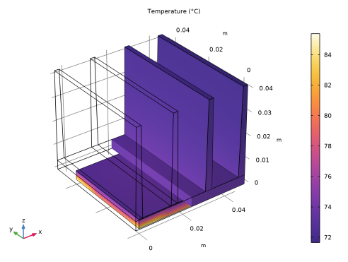
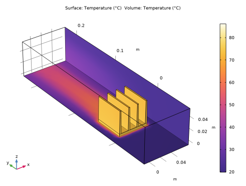
In the Settings window for 3D Plot Group, type Temperature of the channel walls and heat sink in the Label text field.
|
|
3
|
|
1
|
|
2
|
|
1
|
|
2
|
|
1
|
|
2
|
Go to the Add Physics window.
|
|
3
|
|
4
|
Click the Add to Component 1 button in the window toolbar.
|
|
5
|
|
1
|
|
2
|
From the Selection list, choose Exterior boundaries without heat sink base (Heat Sink - Straight Fins 1).
|
|
3
|
To add the channel walls, click the Paste Selection button and type 1 3 4 44 (note that boundaries 1 and 4 have been hidden previously and are not visible in the graphics window).
|
|
1
|
|
2
|
|
3
|
|
1
|
|
2
|
In the Settings window for Diffuse Surface, in the Graphics window toolbar, click
|
|
1
|
|
2
|
Go to the Add Multiphysics window.
|
|
3
|
In the tree, select No Predefined Multiphysics Available for the Selected Physics Interfaces.
|
|
4
|
Find the Select the physics interfaces you want to couple subsection. In the table, clear the Couple checkbox for Laminar Flow (spf).
|
|
5
|
|
6
|
Click the Add to Component button in the window toolbar.
|
|
7
|
|
1
|
|
2
|
|
3
|
Locate the Geometric Entity Selection section. From the Geometric entity level list, choose Boundary.
|
|
4
|
From the Selection list, choose Exterior boundaries without heat sink base (Heat Sink - Straight Fins 1).
|
|
5
|
Locate the Material Contents section. In the table, enter the following settings:
|
|
1
|
|
2
|
|
3
|
Locate the Geometric Entity Selection section. From the Geometric entity level list, choose Boundary.
|
|
4
|
|
6
|
|
7
|
Locate the Material Contents section. In the table, enter the following settings:
|
|
1
|
|
2
|
|
1
|
|
2
|
|
3
|
In the Solve for column of the table, under Component 1 (comp1), clear the checkbox for Surface-to-Surface Radiation (rad).
|
|
4
|
In the Solve for column of the table, under Component 1 (comp1) > Multiphysics, clear the checkbox for Heat Transfer with Surface-to-Surface Radiation 1 (htrad1).
|
|
1
|
|
2
|
Go to the Add Study window.
|
|
3
|
|
4
|
Right-click and choose Add Study.
|
|
5
|
|
1
|
|
2
|
|
1
|
|
2
|
|
1
|
In the Model Builder window, expand the Results > Temperature and Fluid Flow (nitf1) 1 > Fluid Flow node, then click Filter 1.
|
|
2
|
|
3
|
|
4
|
|
1
|
|
2
|
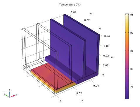
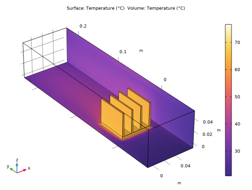
In the Settings window for 3D Plot Group, type Temperature of the channel walls and heat sink, with radiation in the Label text field.
|
|
3
|
|
1
|
In the Model Builder window, expand the Temperature of the channel walls and heat sink, with radiation node.
|
|
2
|
|
1
|
In the Model Builder window, under Results click Temperature of the channel walls and heat sink, with radiation.
|
|
2
|
|
1
|
|
2
|
Go to the Result Templates window.
|
|
3
|
In the tree, select Study 2 With Radiation/Solution 2 (sol2) > Heat Transfer in Solids and Fluids > Contact Temperature (ht).
|
|
4
|
Click the Add Result Template button in the window toolbar.
|
|
5
|
|
1
|
In the Model Builder window, expand the Results > Contact Temperature (ht) node, then click Surface Slit 1.
|
|
2
|