|
|
|

|
•
|
Check the Auxiliary sweep checkbox available in the Study Extensions section of the corresponding study and specify the desired values of the flow Mach number parameter.
|
|
•
|
|
•
|
|
1
|
|
2
|
In the Select Physics tree, select Fluid Flow > Single-Phase Flow > Turbulent Flow > Turbulent Flow, SST (spf).
|
|
3
|
Click Add.
|
|
4
|
Click
|
|
5
|
In the Select Study tree, select Preset Studies for Selected Physics Interfaces > Stationary with Initialization.
|
|
6
|
Click
|
|
1
|
|
2
|
|
3
|
Click
|
|
4
|
Browse to the model’s Application Libraries folder and double-click the file helmholtz_resonator_with_flow_parameters.txt.
|
|
1
|
|
2
|
|
3
|
|
4
|
|
5
|
|
6
|
Click to expand the Layers section. In the table, enter the following settings:
|
|
7
|
Clear the Layers on side checkbox.
|
|
8
|
Select the Layers on bottom checkbox.
|
|
9
|
Select the Layers on top checkbox.
|
|
1
|
|
2
|
|
3
|
|
4
|
|
5
|
|
6
|
|
1
|
|
2
|
|
3
|
|
4
|
|
5
|
|
6
|
|
1
|
|
2
|
|
3
|
|
4
|
|
5
|
|
1
|
|
2
|
|
3
|
|
4
|
|
5
|
|
6
|
Click
|
|
1
|
|
2
|
|
3
|
|
4
|
|
5
|
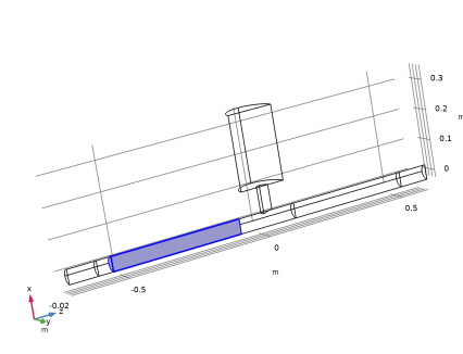
On the object cyl1, select Boundaries 12 and 15 only.
|
|
6
|
|
7
|
Click
|
|
8
|
|
1
|
|
2
|
|
3
|
|
4
|
|
5
|
Click
|
|
1
|
|
2
|
Click in the Graphics window and then press Ctrl+A to select all objects.
|
|
1
|
|
2
|
|
3
|
|
1
|
|
2
|
Select the object uni1 only.
|
|
3
|
|
4
|
|
5
|
Click
|
|
1
|
|
2
|
|
3
|
|
4
|
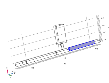
On the object par1, select Domains 2, 4, 6, 8, 10, 12, 14, and 16 only.
|
|
5
|
|
1
|
|
2
|
|
3
|
|
5
|
|
1
|
|
2
|
|
3
|
|
5
|
|
1
|
|
2
|
Go to the Add Material window.
|
|
3
|
|
4
|
Click the Add to Component button in the window toolbar.
|
|
5
|
|
1
|
|
2
|
|
1
|
|
2
|
|
3
|
|
1
|
|
1
|
|
3
|
|
4
|
From the list, choose Fully developed flow.
|
|
5
|
|
1
|
|
2
|
|
1
|
|
1
|
|
2
|
|
3
|
|
4
|
|
1
|
|
2
|
|
3
|
|
4
|
Click the Custom button.
|
|
5
|
|
6
|
|
7
|
|
8
|
|
9
|
|
1
|
|
2
|
|
3
|
|
1
|
|
3
|
|
4
|
|
1
|
|
1
|
|
2
|
|
3
|
|
1
|
|
2
|
|
3
|
|
4
|
|
5
|
|
6
|
Select the Reverse direction checkbox.
|
|
1
|
|
2
|
|
3
|
|
1
|
|
2
|
|
3
|
|
1
|
|
2
|
|
3
|
|
1
|
|
2
|
|
3
|
|
4
|
|
5
|
|
6
|
Select the Reverse direction checkbox.
|
|
1
|
|
2
|
|
3
|
|
1
|
|
2
|
|
3
|
|
5
|
|
6
|
Locate the Element Size Parameters section.
|
|
7
|
|
1
|
|
2
|
In the Settings window for Boundary Layer Properties, locate the Geometric Entity Selection section.
|
|
3
|
|
4
|
|
5
|
|
1
|
|
2
|
|
3
|
|
1
|
|
2
|
|
3
|
Select the Auxiliary sweep checkbox.
|
|
4
|
Click
|
|
1
|
|
2
|
Click
|
|
1
|
|
2
|
|
3
|
|
4
|
|
5
|
|
6
|
|
7
|
|
8
|
|
1
|
|
2
|
|
1
|
|
2
|
|
3
|
|
5
|
|
1
|
|
2
|
|
1
|
|
2
|
|
1
|
|
2
|
|
3
|
|
4
|
|
1
|
|
2
|
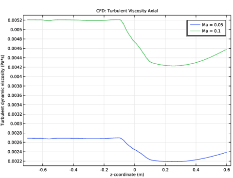
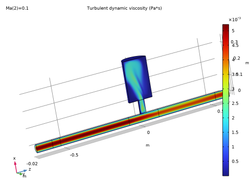
In the Settings window for 1D Plot Group, type CFD: Turbulent Viscosity Axial in the Label text field.
|
|
3
|
|
4
|
|
1
|
|
2
|
|
3
|
|
4
|
|
5
|
|
6
|
|
7
|
|
8
|
|
9
|
|
1
|
|
2
|
Go to the Add Physics window.
|
|
3
|
|
4
|
Find the Physics interfaces in study subsection. In the table, clear the Solve checkbox for Study 1 - CFD.
|
|
5
|
Click the Add to Component 1 button in the window toolbar.
|
|
6
|
|
1
|
In the Physics toolbar, click
|
|
2
|
|
3
|
|
4
|
|
1
|
|
2
|
|
1
|
|
2
|
|
3
|
Click the Custom button.
|
|
4
|
|
5
|
|
1
|
|
2
|
|
3
|
|
1
|
|
2
|
|
3
|
|
5
|
|
6
|
Locate the Element Size Parameters section.
|
|
7
|
|
8
|
|
1
|
|
2
|
|
3
|
|
4
|
Click
|
|
1
|
|
2
|
|
3
|
Clear the Smooth transition to interior mesh checkbox.
|
|
1
|
|
2
|
In the Settings window for Boundary Layer Properties, locate the Geometric Entity Selection section.
|
|
3
|
|
4
|
|
5
|
|
6
|
|
7
|
|
1
|
|
2
|
Go to the Add Study window.
|
|
3
|
Find the Physics interfaces in study subsection. In the table, clear the Solve checkboxes for Turbulent Flow, SST (spf) and Linearized Navier–Stokes, Frequency Domain (lnsf).
|
|
4
|
Find the Studies subsection. In the Select Study tree, select Preset Studies for Selected Multiphysics > Mapping.
|
|
5
|
Click the Add Study button in the window toolbar.
|
|
6
|
|
1
|
|
2
|
|
3
|
|
4
|
|
5
|
|
6
|
|
7
|
|
1
|
|
2
|
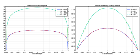
In the Settings window for 1D Plot Group, type Mapping Comparison: z velocity in the Label text field.
|
|
3
|
|
1
|
|
2
|
|
3
|
Click to select the
|
|
5
|
|
6
|
|
7
|
|
8
|
|
9
|
|
10
|
|
1
|
|
2
|
|
3
|
|
5
|
Click Replace Expression in the upper-right corner of the y-Axis Data section. From the menu, choose Component 1 (comp1) > Background Fluid Flow Coupling 1 > Mapped velocity - m/s > bffc1.u_mapz - Mapped velocity, z-component.
|
|
6
|
|
7
|
|
8
|
Click to expand the Coloring and Style section. Find the Line style subsection. From the Line list, choose Dashed.
|
|
9
|
|
10
|
|
11
|
|
12
|
|
1
|
|
2
|
|
3
|
In the Settings window for 1D Plot Group, type Mapping Comparison: Dynamic Viscosity in the Label text field.
|
|
1
|
|
2
|
|
3
|
|
1
|
|
2
|
In the Settings window for Line Graph, click Replace Expression in the upper-right corner of the y-Axis Data section. From the menu, choose Component 1 (comp1) > Background Fluid Flow Coupling 1 > bffc1.mu_eff_map - Mapped turbulent viscosity - Pa·s.
|
|
3
|
|
1
|
In the Model Builder window, under Component 1 (comp1) right-click Definitions and choose Variables.
|
|
2
|
|
3
|
|
4
|
Browse to the model’s Application Libraries folder and double-click the file helmholtz_resonator_with_flow_variables.txt.
|
|
1
|
|
2
|
|
3
|
|
5
|
|
1
|
|
2
|
|
3
|
|
5
|
|
1
|
|
1
|
|
2
|
|
3
|
|
4
|
|
1
|
|
2
|
|
3
|
|
1
|
|
3
|
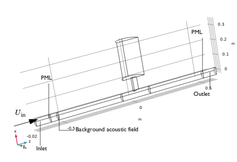
In the Settings window for Background Acoustic Fields, locate the Background Acoustic Fields section.
|
|
4
|
|
5
|
|
6
|
|
1
|
|
2
|
Go to the Add Study window.
|
|
3
|
Find the Physics interfaces in study subsection. In the table, clear the Solve checkbox for Turbulent Flow, SST (spf).
|
|
4
|
Find the Multiphysics couplings in study subsection. In the table, clear the Solve checkbox for Background Fluid Flow Coupling 1 (bffc1).
|
|
5
|
|
6
|
Click the Add Study button in the window toolbar.
|
|
7
|
|
1
|
|
2
|
|
3
|
Click to expand the Values of Dependent Variables section. Find the Values of variables not solved for subsection. From the Settings list, choose User controlled.
|
|
4
|
|
5
|
|
6
|
|
7
|
Click to expand the Mesh Selection section. Add an auxiliary sweep to solve for the two Mach numbers.
|
|
8
|
|
9
|
Click
|
|
11
|
|
12
|
|
13
|
|
14
|
|
15
|
Clear the Generate default plots checkbox.
|
|
16
|
|
1
|
|
2
|
|
3
|
In the Model Builder window, expand the Study 3 - Acoustics, Ma = 0.05 and Ma = 0.1 > Solver Configurations > Solution 4 (sol4) > Stationary Solver 1 node.
|
|
4
|
Right-click Study 3 - Acoustics, Ma = 0.05 and Ma = 0.1 > Solver Configurations > Solution 4 (sol4) > Stationary Solver 1 > Suggested Iterative Solver (GMRES with Direct Precond.) (lnsf) and choose Enable.
|
|
5
|
|
1
|
|
2
|
Go to the Add Physics window.
|
|
3
|
Find the Physics interfaces in study subsection. In the table, clear the Solve checkboxes for Study 1 - CFD, Study 2 - Mapping, and Study 3 - Acoustics, Ma = 0.05 and Ma = 0.1.
|
|
4
|
|
5
|
Click the Add to Component 1 button in the window toolbar.
|
|
6
|
|
1
|
|
3
|
|
4
|
|
5
|
|
1
|
|
3
|
|
4
|
|
5
|
|
6
|
|
1
|
|
2
|
Go to the Add Study window.
|
|
3
|
Find the Physics interfaces in study subsection. In the table, clear the Solve checkboxes for Turbulent Flow, SST (spf) and Linearized Navier–Stokes, Frequency Domain (lnsf).
|
|
4
|
Find the Multiphysics couplings in study subsection. In the table, clear the Solve checkbox for Background Fluid Flow Coupling 1 (bffc1).
|
|
5
|
|
6
|
Click the Add Study button in the window toolbar.
|
|
7
|
|
1
|
|
2
|
|
3
|
|
4
|
|
5
|
Clear the Generate default plots checkbox.
|
|
6
|
|
7
|
|
1
|
|
2
|
|
3
|
Locate the Data section. From the Dataset list, choose Study 4 - Acoustics, Ma = 0/Solution 5 (sol5).
|
|
4
|
|
5
|
|
7
|
Select the Apply to dataset edges checkbox.
|
|
1
|
|
2
|
|
3
|
|
4
|
|
5
|
|
6
|
|
1
|
|
2
|
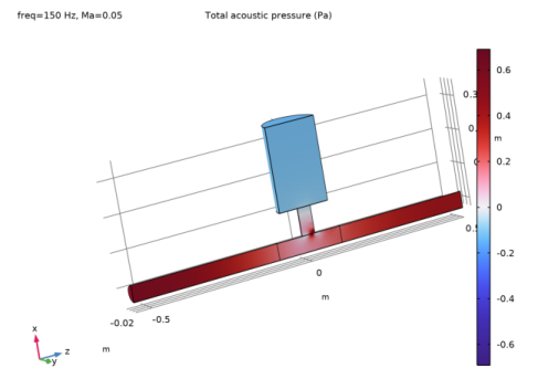
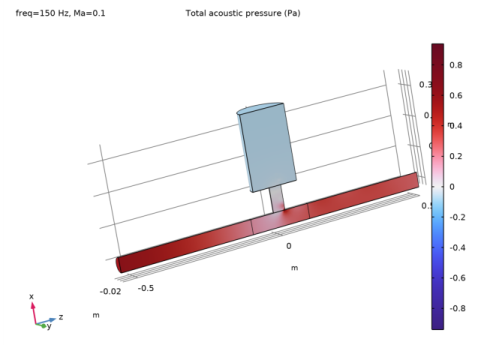
In the Settings window for 3D Plot Group, type Acoustics: Pressure, Ma = 0.1 in the Label text field.
|
|
3
|
Locate the Data section. From the Dataset list, choose Study 3 - Acoustics, Ma = 0.05 and Ma = 0.1/Solution 4 (sol4).
|
|
4
|
|
5
|
|
7
|
Select the Apply to dataset edges checkbox.
|
|
1
|
|
2
|
|
3
|
|
4
|
|
5
|
|
6
|
|
1
|
|
2
|
|
3
|
In the Settings window for 3D Plot Group, type Acoustics: Sound Pressure Level, Ma = 0.05 in the Label text field.
|
|
4
|
|
1
|
|
2
|
|
3
|
|
4
|
|
5
|
|
6
|
|
7
|
|
8
|
|
1
|
|
2
|
|
3
|
|
4
|
|
5
|
Locate the Plot Settings section.
|
|
6
|
|
7
|
|
8
|
|
9
|
|
10
|
|
11
|
|
12
|
|
1
|
|
2
|
|
3
|
|
4
|
Locate the y-Axis Data section. In the table, enter the following settings:
|
|
5
|
Click to expand the Coloring and Style section. Find the Line markers subsection. From the Marker list, choose Point.
|
|
1
|
|
2
|
|
3
|
|
4
|
Locate the y-Axis Data section. In the table, enter the following settings:
|
|
5
|
|
6
|
Locate the Coloring and Style section. Find the Line markers subsection. From the Marker list, choose Point.
|
|
1
|
|
2
|
In the Settings window for Wall Distance Initialization, locate the Physics and Variables Selection section.
|
|
3
|
Select the Modify model configuration for study step checkbox.
|
|
4
|
In the tree, select Component 1 (comp1) > Definitions > Artificial Domains > Perfectly Matched Layer 1 (pml1).
|
|
5
|
Right-click and choose Disable.
|
|
1
|
|
2
|
|
3
|
Select the Modify model configuration for study step checkbox.
|
|
4
|
In the tree, select Component 1 (comp1) > Definitions > Artificial Domains > Perfectly Matched Layer 1 (pml1).
|
|
5
|
Right-click and choose Disable.
|