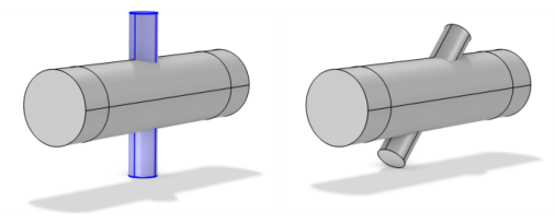
Use the Rotate (

) node to create one or multiple rotated copies with varying rotation angles, as shown in
Figure 7-92 and
Figure 7-93.
To rotate geometry objects, in the Geometry toolbar, from the
Transforms (

) menu, select
Rotate (

). You can also right-click the
Geometry or a
Work Plane feature to add this from the
Transforms submenu. Then enter the properties of the rotate operation using the following sections:
From the Input objects list, choose
Manual (default) to select the geometry objects that you want to rotate in the
Graphics window. Click the
Activate Selection button to toggle between turning ON

and OFF

the
Input objects selections. Alternatively, choose
All objects to select all objects or choose
All nonconstruction objects to automatically select all objects that have not been marked as
Construction Geometry. If the geometry sequence includes user-defined selections above the
Rotate node, you can choose one of the selections from the
Input objects list.
Select the Keep input objects checkbox to use the selected geometry objects for further geometry operations.
In 2D, specify an Angle (in degrees; default: 0) for the rotation. To get several rotated objects, enter a list of angles separated with commas or spaces or using the
range function. Click the
Range button (

) to define a range of angles using the
Range dialog. For example,
range(0,45,315) creates eight objects, one at the original position and seven rotated copies at 45 degrees distance around a full 360 degrees circle.
From the Specify list, choose
Axis of rotation (the default,
Euler angles (Z-X-Z), or
Edge as the way to specify the rotation.
|
•
|
For Axis of rotation, select an Axis type: xw-axis, yw-axis, zw-axis (the default), Cartesian, or Spherical. For any choice, enter an Angle (SI unit: degrees; default 0) to specify the rotation (see 2D Settings above). If Cartesian is selected, enter Cartesian coordinates values for x, y, and z (default values 0, 0, and 1, respectively, corresponding to the global z-axis) to specify the axis vector. If Spherical is selected, specify the axis vector using spherical angles theta and phi in degrees (default: 0). 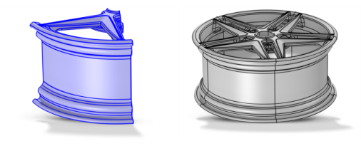
|
|
•
|
For Euler angles (Z-X-Z), enter values for the intrinsic Z-X-Z Euler angles α, β, and γ in the corresponding text fields (in degrees; the default values are 0).
|
|
•
|
For Edge, choose a straight edge as the axis of rotation and add it to the Straight edge list. Then enter an Angle (SI unit: degrees; default 0) to specify the rotation angle.
|
From the Specify list, choose
Position (the default) or
Vertex. When you specify the position, enter the center of the rotation in the
x and
y (for 2D);
r and
z (in 2D axial symmetry); and
xw and
yw in work plane fields. For
Vertex, select a point in the
Graphics window. Click the
Activate Selection button to toggle between turning ON

and OFF

the
Center of rotation selections.
From the Specify list, choose
Coordinates (the default) or
Vertex. When you specify the position, enter a point on the rotation axis in the
x,
y, and
z fields (default 0,0,0). For
Vertex, select a point in the
Graphics window. Click the
Activate Selection button to toggle between turning ON

and OFF

the
Point on axis of rotation selections.
The coordinate system in which the point coordinates and axis of rotation above are interpreted (in 3D geometries only). From the Take work plane from list, select
This sequence (the default) to use a work plane earlier in the same geometry sequence, or choose a part instance earlier in the sequence to choose a work plane from that part. From the
Work plane list, select
xy-plane (the default, for a standard global Cartesian coordinate system) or select any work plane defined above this node in the geometry sequence. If you choose a work plane, the work plane and its coordinate system appears in the
Graphics window, using an extra coordinate triad with the directions
xw,
yw, and
zw (which are then used to specify the rotation axis position).
Select the Resulting objects selection checkbox to create predefined selections (for all levels — objects, domains, boundaries, edges, and points — that are applicable) in subsequent nodes in the geometry sequence. To also make all or one of the types of resulting entities (domains, boundaries, edges, and points) that the resulting objects consist of available as selections in all applicable selection lists (in physics and materials settings, for example), choose an option from the
Show in physics (
Show in instances if in a geometry part,
Show in 3D if in a work plane’s plane geometry) list:
All levels,
Domain selection,
Boundary selection,
Edge selection, or
Point selection. The default is
Domain selection, which is suitable for use with materials and physics defined in domains. For use with a boundary condition, for example, choose
Boundary selection. These selections do not appear as separate selection nodes in the model tree. Select
Off to not make any selection available outside of the geometry sequence. From the
Color list, choose a color for highlighting the resulting objects selection. See
Selection Colors.
If you have Named Selections that include entities on the input objects, select the
Propagate selections to resulting objects (selected by default) checkbox to update the selections to corresponding entities on the output objects, when possible. Clear the checkbox to not propagate the selection to the resulting objects. This can be useful in combination with selecting the
Keep input objects checkbox so that the selections refer only to the input objects.
Select the Create index attribute checkbox to assign 1-based values to the output objects that correspond to the index in the object’s name. The default attribute tag name is listed in the
Attribute tag edit field. The name can be changed. The attribute tag can be used in expressions in
Logical Expression Selection (Geometry Sequences) and
Logical Expression (in Definitions) to quickly select some of the rotated objects.
From the Construction geometry list choose
On to make the resulting objects available only in the feature’s geometry sequence. The default option
Inherit means that the resulting objects become construction geometry if all input objects are construction geometry. Choose
Off to never output construction geometry objects. For more information, see
Construction Geometry.