Tsai and Wu (Ref. 94,
Ref. 107) proposed a stress-dependent criterion intended at modeling failure in composites. Under the Tsai–Wu criterion, failure occurs when a given quadratic function of stress is greater than zero. The failure criterion is given by
where, σ is the stress tensor,
F a fourth rank tensor (SI unit: 1/Pa
2) and
f is a second rank tensor (SI unit: 1/Pa). For the Tsai–Wu criterion, failure occurs when
g(σ) ≥ 0.
Certain constraints ensure that the failure surface g(σ) =
0 forms a closed ellipsoid in the stress space. Also, thermodynamic considerations restrict the value of some components of the fourth rank tensor. These restrictions are summarized as (no index summation)
 and
and 
The failure index is computed from the failure criterion as
The damage index is given by a Boolean expression based on the failure criterion
here di =
1 means damage, and
di =
0 represents a healthy material.
The safety factor,
sf, also called
reserve factor or
strength ratio, is computed by scaling the stress tensor such as the failure criterion is equal to zero
For an isotropic criterion, such as the von Mises criterion, g(σ) =
σmises/σts − 1, the safety factor is given by
sf =
σts/σmises.
The margin of safety (
Ref. 107) is then computed from the safety factor
sf as
Use the Safety subnode to set up variables which can be used to check the risk of failure according to various criteria. It can be used in combination with
Linear Elastic Material,
Linear Elastic Material, Layered, or
Nonlinear Elastic Materials.
Add any number of Safety subnodes to a single material model; the contents of these features will not affect the analysis results because they do not account for postfailure analysis.
Add Safety subnodes after having performed an analysis and just do an
Update Solution in order to access to the new variables for results evaluation.
Add a Safety subnode to calculate the safety factor for a specified criterion. When multiple
Safety subnodes are added, additional built-in variables become available. These additional variables—
combined safety factor,
combined failure index,
combined damage index, and
combined margin of safety—offer a conservative approach to safety assessment.
For this anisotropic criterion, enter 21 coefficients to define the 6-by-6 matrix F, and six coefficients to define the vector
f. The failure criterion is evaluated from the expression
here, σij are the stress tensor components given in the local coordinate system of the parent node.
For this orthotropic criterion, enter nine coefficients corresponding to the tensile strengths σtsi, compressive strengths
σcsi, and shear strengths
σssij given in the local coordinate system of the parent node. The Tsai–Wu coefficients are then computed from
For this orthotropic criterion, enter six coefficients corresponding to the tensile strengths σtsi and shear strengths
σssij given in the local coordinate system of the parent node. The equivalent coefficients for the
Anisotropic Tsai–Wu Criterion are then computed from
 , or
, or 
 , or
, or 
 , or
, or 
all the other coefficients in F and
f tensors are set to zero. See also
Hill Criterion.
and the F12 term is modified as follows
For this orthotropic criterion, enter nine coefficients corresponding to the tensile strengths σtsi, compressive strengths
σcsi, and shear strengths
σssij given in the local coordinate system of the parent node. The equivalent coefficients for the
Anisotropic Tsai–Wu Criterion are then computed from
For Jenkins orthotropic criterion, enter nine coefficients corresponding to the tensile strengths σtsi, compressive strengths
σcsi, and shear strengths
σssij given in the local coordinate system of the parent node. The failure criterion is then computed from
here, εsi is either the tensile strength or the compressive strength depending whether the stress in the
i direction,
σi, is positive or negative. The absolute value of the shear stress
σij in the
ij-plane is compared to the corresponding shear strength
σssij.
here, εsi is either the ultimate tensile strain or the ultimate compressive strain depending whether the strain in the
i direction,
εi, is positive or negative. The absolute value of the shear strain
γij in the
ij-plane is compared to the corresponding ultimate shear strain
γssij.
 , or
, or 
 , or
, or 
 , or
, or 
 , or
, or 
 , or
, or 
The equivalent von Mises stress σmises is defined from the deviatoric stress tensor, see the section about plasticity and
von Mises Criterion. For ductile materials the tensile strength corresponds to the yield stress, while for brittle materials it corresponds to the failure strength.
Here, the Tresca equivalent stress is defined in terms of principal stresses, σtresca =
σ1 − σ3; see
Tresca Criterion. For ductile materials the tensile strength corresponds to the yield stress, while for brittle materials it corresponds to the failure strength.
here, σs is either the tensile strength or the compressive strength depending whether the principal stress,
σpi, is positive or negative. For ductile materials the tensile strength corresponds to the yield stress, while for brittle materials it corresponds to the failure strength.
Here, εs is either the ultimate tensile strain or the ultimate compressive strain depending on whether the principal strain,
εpi, is positive or negative. For ductile materials the ultimate tensile strain corresponds to the strain at yielding, while for brittle materials it corresponds to the strain at failure.
The Mohr–Coulomb criterion is similar to the Tresca criterion, as the failure criterion is given in terms of principal stresses, see Mohr–Coulomb Criterion for soil plasticity. For this isotropic criterion, enter the cohesion
c, and the angle of internal friction
ϕ. The failure criterion is then computed from
 and
and 
The material parameters α and
k are related to the cohesion
c and angle of internal friction
ϕ in the Mohr–Coulomb criterion, see
Drucker–Prager Criterion for details. Also, the cohesion and the angle of internal friction can be related to the tensile and compressive strengths, see
Mohr–Coulomb Criterion for details. The failure index is computed from
Griffith criterion (Ref. 108) is intended to study the fracture of brittle materials.
where the parameter m is computed from the ratio
The parameters k1,
k2, and
k3 are computed from the uniaxial compressive strength
σcs, the uniaxial tensile strength
σts, and the biaxial compressive strength
σbc, see
Bresler–Pister Criterion for details. The failure index is computed from
here, σcs is the compressive strength,
σts is tensile strength, and
σbc is the biaxial compressive strength. The function
r(
θ) describes the segment of an ellipse on the octahedral plane; see
Willam–Warnke Criterion for details. The failure index is computed from
In this formulation, the parameters a and
b are positive and dimensionless, and
σcs is the compressive strength for concrete (also with a positive sign). The dimensionless function
λ(
θ) depends on the Lode angle
θ and two positive parameters
k1 and
k2; see
Ottosen Criterion for details. The failure index is computed from
To replicate the von Mises Isotropic criterion with a tensile strength of
350 MPa, define
g(S) as
solid.mises/350[MPa]-1 and
sf(S) as
350[MPa]/(solid.mises+eps).
The Safety subnode calculates the failure index, damage index, safety factor, and margin of safety for a specified criterion. When multiple
Safety subnodes are added, additional built-in variables become available. The
combined safety factor,
combined failure index,
combined damage index, and
combined margin of safety, offer a conservative approach to safety assessment for multiple failure criteria.
The combined failure criterion is estimated by selecting the most critical failure criterion for a given multiaxial stress state
The combined failure index is computed accordingly
The combined damage index is given by a Boolean expression based on the combined failure index
where dicom =
1 represents a damaged material, and
dicom =
0 represents a healthy material.
The combined safety factor is obtained from the smallest safety factor among the added criteria
The combined margin of safety is then computed from the combined safety factor
sf,com as
|
|
The internal variables ficom, dicom, sf,com, and mscom are named item.f_i_com, item.d_i_com, item.s_f_com, and item.m_s_com, respectively. Here, item is the name of the parent node (for instance, solid.lemm1 for a Linear Elastic material).
|
Table 3-8 shows failure criterion and considered failure modes by that criterion.
 for
for 
 for
for 
 for
for 
 for
for 
 for
for 
 for
for 
 for
for 
 for
for 
 for
for 
 for
for 
 for
for 
 for
for 
 for
for 
The plane stress version of the Hashin criterion is obtained by setting σ13 = σ23 = σ33 = 0, however, the interlaminar failure cannot be predicted.
 for
for 
where Ef1 is the Young’s modulus of the fiber in the longitudinal direction,
νf12 is the in-plane Poisson’s ratio of the fiber, and
mσf is the
mean stress magnification factor.
 for
for 
 for
for 
where ptl is the slope of the in-plane fracture envelope in tension, and
σ1D is the
linear degradation stress.
where pcl is the slope of the in-plane fracture envelope in compression,
RAtt is the fracture resistance against transverse shear loading, and
σcss12 is the modified shear strength.
where pct is the slope of the transverse fracture envelope in compression.
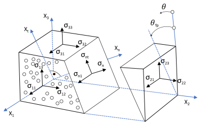
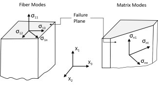
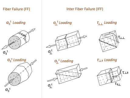
This criterion is used for accurate predicting the failure of unidirectional FRP laminates with in-plane stress state. The criterion is composed of six phenomenological failure modes describing matrix and fiber failure accurately without the use of curve-fitting parameters (Ref. 112), and it assumes a fragile fracture for the matrix failure in compression. This criterion implements the action plane concept according to the Mohr–Coulomb theory. This failure theory considers failure modes based on the fiber kinking due to misalignment and on the tensile matrix cracking associated with interlaminar crack propagation.
 for
for 
where τeff,t and
τeff,l are effective shear stresses in transverse and longitudinal directions, respectively, and
σiss12 is the longitudinal in situ shear strength. The effective shear stresses are functions of the fracture plane angle which is found out by maximizing the Mohr–Coulomb effective stresses.
 for
for 
where σits2 is in situ tensile strength, and
r is a material constant based on fracture toughness.
 for
for 
 for
for 
 for
for 
where σmij are the ply stresses transformed in the misalignment coordinate frame, and
ηl is a nondimensional parameter based on the failure strength and fracture plane angle under uniaxial transverse compression.
where the effective shear stresses in transverse and longitudinal directions, τmeff,t and
τmeff,l, are calculated from stresses in the misalignment coordinate frame.


 for
for