Add a Filter subnode under
Enclosed Cavity to indicate that a certain part of a boundary does not enclose the fluid. A boundary region excluded by a filter selection is ignored in the volume computation, and the pressure load is not applied on such region.
Only boundaries selected in the parent Enclosed Cavity node can be selected in the
Filter subnode. Select only boundaries on which a filter expression should be applied. Boundaries which have no filter condition are always included.
Enter a Boolean expression for the Logical expression for inclusion, undeformed configuration ef,ref. The expression should evaluate to 1 (include) or 0 (exclude). The filter expression affects the computation of the reference volume, and it must not depend of the deformation.
Enter a Boolean expression for the Logical expression for inclusion, deformed configuration ef. The expression should evaluate to 1 (include) or 0 (exclude). The filter expression affects the computation of the volume in the deformed configuration. No pressure forces from the
Fluid (Enclosed Cavity) node or
Prescribed Pressure (Enclosed Cavity) node are applied on boundary regions, where the Boolean expression evaluates to 0.
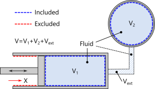
Consider the piston–cylinder assembly shown in Figure 4-1, where the piston moves in the
X direction. In this case, a filter expression must be applied on the cylinder wall. To track the piston position, it is convenient to define an average operator (material frame) on a suitable reference point, edge, or boundary on the piston’s head.
Assuming that the operator is called aveop1, the Boolean expression for the
Logical expression for inclusion, undeformed configuration ef,ref reads
X>=aveop1(X), and the
Logical expression for inclusion, deformed configuration ef reads
X>=aveop1(X+u), where
u is the piston displacement in the
X direction.
In a geometric nonlinear study, the expression X+u is equivalent to the spatial coordinate
x.
Physics tab with Enclosed Cavity selected in the model tree: