PDF

Boundary Layer Meshing — Exploring the Settings
Introduction
A boundary-layer mesh is a type of structured anisotropic mesh where the mesh elements have high aspect ratios. For example, in CFD applications close to no-slip wall boundaries, the flow is highly anisotropic, and a much finer mesh is needed to resolve high gradients.
With physics-controlled meshing, a boundary-layer mesh is automatically generated for fluid-flow applications, and can easily be generated for other applications. In all cases, the boundary-layer mesh is inserted after the interior mesh, which means that the interior mesh is deformed to accommodate the boundary-layer mesh. This tutorial series focuses on the generation and setup of boundary-layer meshes. Throughout the series, we will also explore key aspects of boundary-layer meshes, such as the height of the boundary layers, the growth rate of elements from the boundary to the interior, and the various techniques for corner handling.
In this tutorial, you will learn how to edit the physics-controlled meshing sequence to modify the settings for the boundary-layer mesh generation. You will discover the methods for controlling the number and distribution of elements in the boundary-layer mesh, and the size of the elements by choosing automatic thickness or by specifying the first layer or the total boundary layer thickness. We will also show how to control the increase in layer thickness from the boundary toward the interior by entering a stretching factor that specifies the increase in thickness between two consecutive boundary layers. The tutorial also details how to create boundary-layer meshes with different properties on different boundaries, how to control the boundary layer generation in sharp corners, and how to visualize the mesh to assess the quality of the elements.
The other tutorial in the series, Boundary Layer Meshing — Adding Boundary Layers to an Imported Mesh, focuses on boundary-layer mesh generation for an imported mesh, including methods for controlling the deformation of the interior mesh. That tutorial also explores how to refine the imported mesh before generating the boundary-layer mesh.
Model Definition
model geometry
The geometry in Figure 1 represents the 2D cross-section of a partially open ball valve in a pipe geometry.
Figure 1: The model geometry of the ball valve with approximate angles for the sharp corners and the boundary conditions.
Domain Equation and Boundary Conditions
A Laminar Flow interface is used in this tutorial to enable the generation of a physics-controlled meshing sequence. Figure 1 shows the specified boundary conditions. An Inlet boundary condition with an inflow velocity is applied on the left boundary, while an Outlet boundary condition is used on the right boundary. All remaining boundaries are wall boundaries. Note that we do not solve for the physics; the physics interface is added only to generate a physics-controlled meshing sequence that we can use as the starting point for exploring the boundary-layer mesh settings.
Application Library path: COMSOL_Multiphysics/Meshing_Tutorials/valve_boundary_layers
Modeling Instructions
From the File menu, choose New.
New
In the New window, click  Model Wizard.
Model Wizard
1
In the Model Wizard window, click  2D.
2
In the Select Physics tree, select Fluid Flow > Single-Phase Flow > Laminar Flow (spf).
3
Click Add.
4
Geometry 1
1
In the Geometry toolbar, click Insert Sequence and choose Insert Sequence.
2
3
In the Geometry toolbar, click  Build All.
Laminar Flow (spf)
We begin by adding the inlet and outlet boundary conditions. The boundary layer mesh will not be inserted for these boundaries when the physics-controlled mesh is generated.
Inlet 1
1
In the Physics toolbar, click  Boundaries and choose Inlet.
2
3
In the Settings window for Inlet, locate the Velocity section.
4
In the U0 text field, type 0.5[m/s].
Outlet 1
1
In the Physics toolbar, click  Boundaries and choose Outlet.
2
Mesh 1
First, we will build the physics-controlled mesh, as determined by the laminar flow physics interface. Later, we will use this as a starting point for exploring the settings for generating the boundary layer mesh.
1
In the Model Builder window, under Component 1 (comp1) click Mesh 1.
2
In the Settings window for Mesh, locate the Physics-Controlled Mesh section.
3
From the Element size list, choose Fine.
4
Click  Build All.
Examine the mesh. We can see that the mesh is finer where the boundary layer mesh is inserted along the wall boundaries. The two corners B, see Figure 1, are meshed with even smaller elements than the other wall boundaries.
Next, we will look into the meshing operations that generated the mesh.
5
In the Model Builder window, right-click Mesh 1 and choose Edit Physics-Induced Sequence.
6
In the Model Builder window, expand the Boundary Layers 1 node.
Boundary Layer Properties 1
You can now see the automatically generated meshing sequence under the Mesh 1 node. It consists of the following operations and attributes:
Size — a global attribute node that controls the size of the elements in the entire sequence. A good practice is to use this node to define the coarsest mesh element size you plan to have in the geometry. You can then add downstream Size attribute nodes as needed to apply finer mesh element size settings on selected entities.
Size 1 — attribute node to control the element size on specified boundaries. Here, it prescribes a finer mesh element size on the wall boundaries.
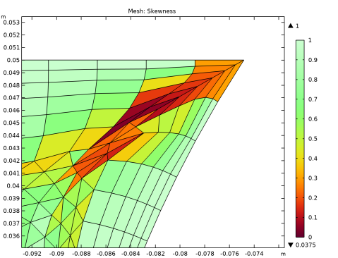
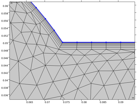
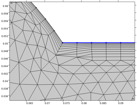
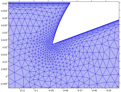
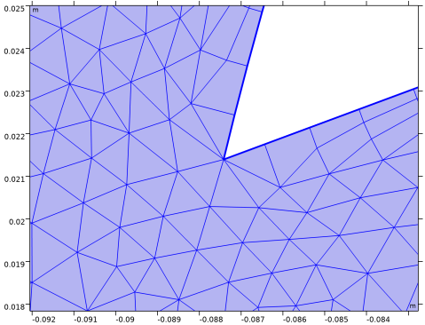
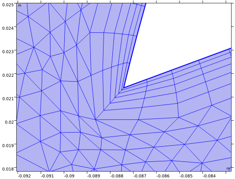
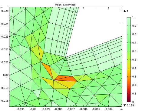
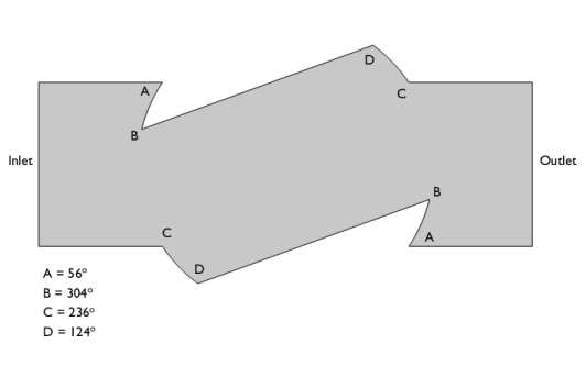
Corner Refinement 1 — attribute node that prescribes a mesh refinement at corners where the adjacent edges form an angle greater than a specified value. It is usually applied to increase the number of elements around corners where the boundary layer mesh is trimmed.
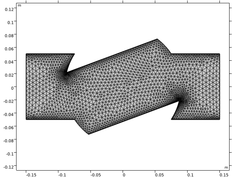
Free Triangular 1 — mesh operation to generate an unstructured triangular mesh in the simulation domain.
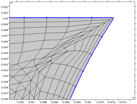
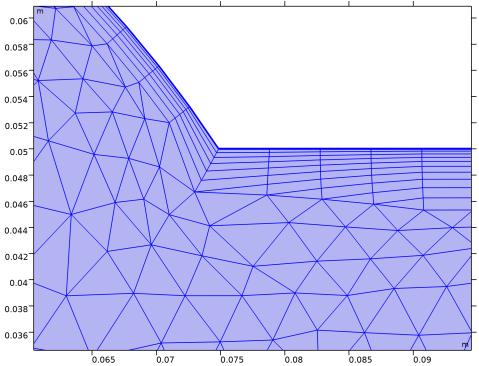
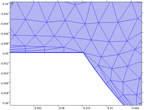
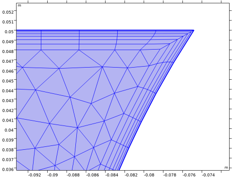
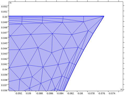
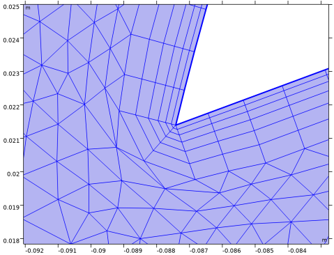
Boundary Layers 1 — mesh operation to insert a boundary layer mesh for selected domains. Contains settings for boundary layer generation in sharp corners.
Boundary Layer Properties 1 — local attribute node that contains the selection of boundaries where the boundary layer mesh should be inserted. It also includes settings for layer height and number of layers. Several nodes can be added to specify different boundary layer characteristics on different boundaries.
1
In the Model Builder window, under Component 1 (comp1) > Mesh 1 > Boundary Layers 1 click Boundary Layer Properties 1.
2
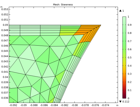
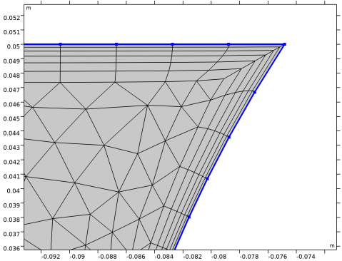
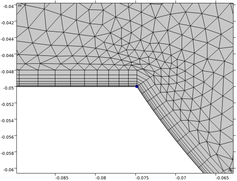
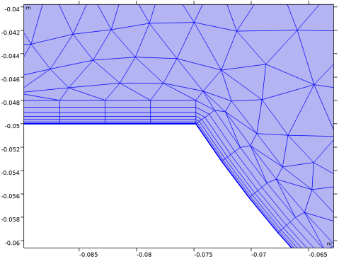
Zoom in around corner C, see Figure 1, in the top right region of the valve to see the inserted boundary layers mesh more clearly.
The boundary layer mesh generated for the laminar flow model consists of two layers of quad elements inserted into the triangular mesh that has been deformed to accommodate the boundary layers. The quad elements have a large aspect ratio, with long element sides several times larger than the short sides. This anisotropy is desired for resolving the variable fields close to the boundaries. Much higher aspect ratios, even close to 100, can be acceptable for solving the equations. Despite the anisotropy these elements have quite good quality since the edges of the quad elements are close to perpendicular.
Other important characteristics of boundary layer meshes are the element thickness and the growth rate for the thickness from the boundary to the interior. Especially for fluid flow applications, the element size should increase as little as possible between layers. In the current mesh, the thickness of the first boundary layer is only slightly less than that of the second layer. Moreover, the triangular mesh has been deformed so that the first layer of triangles is only slightly larger than the neighboring quad layer, and the size of the triangular elements is then gradually increased toward the interior.
Where the boundary layer mesh wraps around the corner, the element sides are skewed, but the quality of these elements is still very good. This could become an issue if the angle between the boundaries at the corner is very large or very small. Further ahead in the tutorial, we will look at the various methods available for generating the boundary layer mesh in sharp corners.
Note that when you switch to manual mesh generation, the selections in the mesh operations will not update automatically if you make significant modifications to the geometry or change the physics setup, for example, by changing the selection for the inlet and outlet boundaries. Because of this, it is always a good practice to review the selections of meshing operations and attributes after such changes and to use named selections.
We will now continue exploring the settings for the number of layers and layer height.
3
In the Settings window for Boundary Layer Properties, locate the Layers section.
4
In the Number of layers text field, type 6 to specify the number of layers in the boundary layer.
5
Click  Build Selected.
With six inserted layers, there is a considerable increase in the total thickness of the boundary layer mesh. This is due to the scaling applied to the automatically determined layer thickness. The meshing algorithm determines an appropriate thickness based on the local element size on the boundaries, and the automatically determined thickness is then multiplied by the Thickness adjustment factor. The current value, 5, of the Thickness adjustment factor has been determined by the software for the laminar flow physics, for which we usually need only a couple of boundary layers that do not have to be very thin.
Information
1
In the Model Builder window, click Information.
When needed to maintain a good mesh quality, the meshing algorithm can locally reduce the thickness of the boundary layer to avoid very low quality elements. If this happens, Information nodes appear under the Boundary Layers node.
2
Zoom in around the coordinates specified in the Settings window for the Information.
The information node notifies that the thickness of the boundary layer was reduced locally to a certain percentage of the target value to avoid low-quality elements.
3
In the Mesh toolbar, click  Plot.
Results
Mesh 1
Notice the element with the dark red color, which indicates a very low quality. To avoid elements of an even lower quality at this corner, the mesher reduced the thickness of the boundary layers.
To avoid these issues when inserting the boundary layer mesh, we can decrease the Thickness adjustment factor.
Mesh 1
Boundary Layer Properties 1
1
In the Model Builder window, under Component 1 (comp1) > Mesh 1 > Boundary Layers 1 click Boundary Layer Properties 1.
2
In the Settings window for Boundary Layer Properties, locate the Layers section.
3
In the Thickness adjustment factor text field, type 1.2.
4
Click  Build Selected.
The boundary layer becomes much thinner since we have reduced the thickness of the first layer. The Information node no longer appears.
Results
Mesh 1
1
In the Model Builder window, under Results > Mesh Plot 1 click Mesh 1.
The mesh quality has also improved at this location, and the boundary layer thickness is now preserved at the corner.
Mesh 1
Boundary Layer Properties 1
1
In the Model Builder window, under Component 1 (comp1) > Mesh 1 > Boundary Layers 1 click Boundary Layer Properties 1.
2
In the Settings window for Boundary Layer Properties, locate the Layers section.
We can also control how the layers’ thickness increases from the boundary toward the interior by entering a stretching factor that specifies the increase in thickness between two consecutive boundary layers. Here, 1.2 means that the thickness increases by 20% from one layer to the next. We will increase this value to obtain a better size transition to the unstructured mesh.
3
In the Stretching factor text field, type 1.3.
4
Click  Build Selected.
The boundary layer mesh is now thicker than after the previous build, and the size of the triangular elements and the neighboring quad elements is closer than before.
Up to this point we have tested the parameters that can influence the automatically determined boundary layer thickness. In the following we will switch to complete manual control.
5
Zoom in around corner C, see Figure 1, in the top right region of the valve.
6
From the Thickness specification list, choose First layer.
7
In the Thickness text field, type 0.15[mm] to specify the thickness of the first element layer.
When calculating the total thickness for the layers, the boundary layer mesher now takes into account the values you have entered for the number of layers, the stretching factor, and the thickness of the first layer.
8
Click  Build Selected.
If you instead specify the total layer thickness, together with the number of layers and the stretching factor, the mesher will calculate the thickness of the first layer.
9
From the Thickness specification list, choose All layers.
10
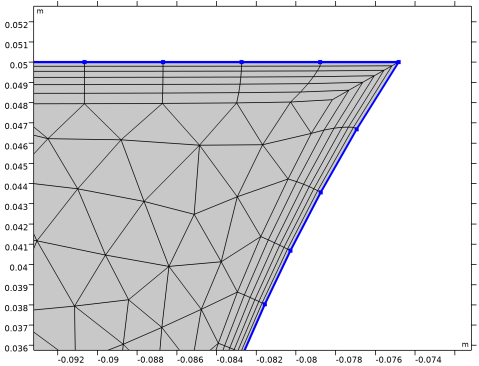
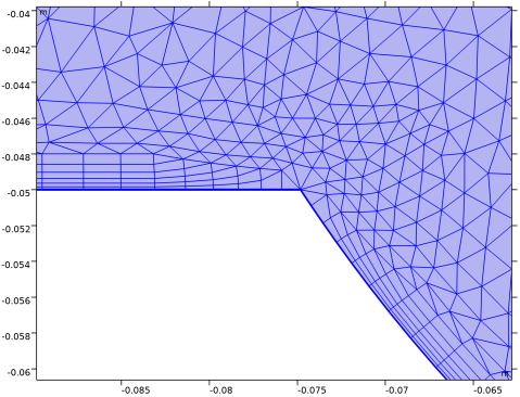
In the Total thickness text field, type 2[mm] to specify the total thickness of layers in the boundary layer.
11
Click  Build Selected.
Note that while the mesher tries to maintain the boundary layer thickness as entered in total thickness or first layer thickness fields, this may not always be possible due to local conditions that may lead to very low element quality. If a significant reduction of layer thickness or number of layers is needed an Information node is always displayed.
Assume that we want to have a different number of layers on one of the top horizontal boundaries. You can do this by adding another Boundary Layer Properties attribute node.
12
Locate the Boundary Selection section. In the list, select 7.
13
Click  Remove from Selection.
The above step is optional since a downstream Boundary Layer Properties node for the same boundary overrides the current one. However, ensuring that only one set of settings applies to a boundary is usually good practice to avoid confusion in more complex cases.
Boundary Layer Properties 2
1
In the Mesh toolbar, click  More Attributes and choose Boundary Layer Properties.
2
3
In the Settings window for Boundary Layer Properties, locate the Layers section.
4
In the Number of layers text field, type 10.
5
Click  Build Selected.
Close to the corner where the edges with different number of boundary layers meet, some quad elements are collapsed into triangles. This is called trimming in the software, and you can control the number of elements that are trimmed between neighboring mesh vertices until the corner is reached.
Boundary Layers 1
1
In the Model Builder window, click Boundary Layers 1.
2
In the Settings window for Boundary Layers, click to expand the Corner Settings section.
With the Maximum layer decrement parameter set to 2, a maximum of two layers can be combined into one at each vertex along the boundary. If you want to have more gradual trimming, you can set the value to 1, which means that one layer at a time will be trimmed.
3
In the Maximum layer decrement text field, type 1.
4
Click  Build Selected.
Notice that the trimming of the boundary layers, and thus the reduction of the thickness starts further away from the corner. This can be important to consider when choosing a value for the maximum layer decrement, as a thin boundary layer could potentially lead to problems with the solution in some applications.
We will now continue exploring the various methods for handling corners when inserting a boundary layer mesh. It is usually only corners with very large or very small angles that need special treatment to avoid problems. Trimming of the boundary layers is one of the available methods for such cases, and it is the default method for meshes generated by physics-controlled meshing due to its robustness. In the current geometry, trimming is applied in the two corners B in Figure 1.
5
Corner B is approximately 304 degrees, which is larger than the default threshold for trimming, 240 degrees. Thus all corners larger than 240 degrees in the geometry will be trimmed when a boundary layer mesh is inserted by physics-controlled meshing.
Notice also the finer mesh around corner B. This mesh refinement is done by the Corner Refinement 1 node that is added to the sequence to counter the loss of resolution due to trimming.
6
Trimming is not applied at this corner since the angle is smaller than the threshold for trimming.
7
In the Trim for angles greater than text field, type 230.
8
Click  Build Selected.
With the boundary layers trimmed, there are now fewer mesh elements around the corner. We can improve this by ensuring that corner refinement also applies to this corner.
Corner Refinement 1
1
In the Model Builder window, click Corner Refinement 1.
2
In the Settings window for Corner Refinement, locate the Angle section.
3
In the Minimum angle between boundaries text field, type 230.
4
Click  Build All.
Boundary Layers 1
1
In the Model Builder window, click Boundary Layers 1.
Notice that the resolution around the corner has increased.
2
The boundary layer elements are connected inside the corner. While this corner is on the narrow side, the angle is about 56 degrees, and it is not that narrow that inserting the boundary layer elements becomes difficult. For even narrower corners, which have an angle of 50 degrees or smaller, trimming is applied by default. You can change this threshold by editing the value for the setting Trim for angles less than.
3
In the Settings window for Boundary Layers, locate the Corner Settings section.
4
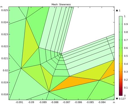
Find the Trimming in narrow corners subsection. In the Trim for angles less than text field, type 65.
5
Click  Build Selected.
The corner is now trimmed. In some cases this may even be the desired option if we do not expect the region inside a narrow corner to have a significant influence on the physics. By trimming in the corners we can then reduce the number of mesh elements, and thereby the computational time.
So far we have looked into how trimming is applied when inserting boundary layer elements around corners with both narrow and large angles. For the latter type of corners there are two additional corner handling methods, which can be useful when you need more boundary layer elements around a corner.
6
The boundary layer mesh is currently trimmed at this corner, and due to the mesh refinement, there are seven mesh elements in the corner.
7
From the Handling of sharp corners list, choose No special handling.
With this option, the corners with large angles will not be treated differently from the surrounding boundaries.
8
Click  Build Selected.
The boundary layer mesh now wraps around the corner with 12 quad elements that connect at the corner. Due to the corner angle these elements are somewhat skewed, resulting in lower element quality.
Notice also that the thickness of the layers is reduced at the corner to avoid that the triangular elements become too deformed. This is the reason for the Information node appearing in the sequence.
If you would like to have even more elements around the sharp corner, you can use splitting as sharp corners handling method. Next, try this option on the current mesh.
9
From the Handling of sharp corners list, choose Splitting.
10
Click  Build Selected.
With the splitting option more quad elements are introduced at the corner, so that where we previously had 12 elements around the corner we now have twice as many. Splitting also improves the element quality, the edges of the quad elements are less skew than in the previous mesh.
11
In the Maximum angle per split text field, type 60.
12
Click  Build Selected.
While this change resulted in one additional column of boundary layer elements around the corner, it may also result in lower quality triangular elements adjoining the quad elements.
Information
1
In the Model Builder window, click Information.
To avoid low quality elements, the mesher reduced the boundary layer thickness around the corner. We can see the element quality in the mesh plot.
Results
Mesh 1
1
In the Model Builder window, under Results > Mesh Plot 1 click Mesh 1.
To improve the quality, we can exclude this corner from the corner refinement, which we do not really need since splitting already provides adequate resolution around the corner.
Mesh 1
Corner Refinement 1
1
In the Model Builder window, under Component 1 (comp1) > Mesh 1 click Corner Refinement 1.
2
In the Settings window for Corner Refinement, locate the Angle section.
3
Select the Filter corners checkbox.
4
5
Locate the Filter Corner Selection section. Click the Exclude these corners button.
6
Click  Build All.
Results
Mesh 1
1
In the Model Builder window, under Results > Mesh Plot 1 click Mesh 1.
Since the triangular elements are now larger, they do not have to be deformed as much as previously when inserting the boundary layer elements. As a result the quality of the final mesh is improved around the corner.
For large and complex models, it is sometimes desired to have complete control over the boundary layers mesh handling in specific corners. You can override the global settings for corner handling by adding Corner Properties attribute nodes to the Boundary Layers node.
2
In the Model Builder window, under Component 1 (comp1) > Mesh 1 click Boundary Layers 1.
Mesh 1
Corner Properties 1
1
In the Mesh toolbar, click  More Attributes and choose Corner Properties.
2
3
In the Settings window for Corner Properties, locate the Corner Properties section.
4
From the Corner handling list, choose Splitting.
Splitting will now be applied at the selected point, regardless of the corner handling method specified in the Boundary Layers 1 node.
5
Click  Build Selected.
Corner Refinement 1
1
In the Model Builder window, under Component 1 (comp1) > Mesh 1 click Corner Refinement 1.
2
In the Settings window for Corner Refinement, locate the Filter Corner Selection section.
3
Click to select the  Activate Selection toggle button.
4
5
Click  Build All.
Boundary Layers 1
In the Model Builder window, click Boundary Layers 1.