PDF

STL Import 2 — Combining Geometry with an Imported Mesh1
Introduction
When working with imported STL meshes, you may run into applications where you want to combine your imported mesh with an imported CAD part, CAD assembly, or with geometry created in COMSOL Multiphysics.
This tutorial series consists of two parts, where the first part, STL Import 1 — Repairing and Combining STL Files, focuses on using available tools to edit imported STL meshes: the different operations for repairing the meshes, combining imported meshes with each other, and generating a volume mesh from the imported surface mesh. This second part of the series describes a workflow for combining the mesh obtained in the first part with a parameterized geometry.
Figure 1: Left: Tetrahedral mesh after repairing, combining, and partitioning imported surface meshes in the first part of the tutorial series. Right: Tetrahedral mesh after combining the mesh from the first part with parameterized geometry created in the second part of the tutorial series.
The STL file format is one of the standard file formats for 3D printing, and it is also often used as a format for exchanging 3D scan data. STL files contain only the triangulated surface, which can also be called a surface mesh, of a 3D object. The triangles in the file are identified by their normals and vertex coordinates and are stitched together using a tolerance to form a faceted representation of the object.
COMSOL Multiphysics supports a variety of operations, for example, moving, scaling and rotating an imported mesh, combining the imported mesh with parameterized geometry to run parametric sweeps, and generating unstructured, structured, and boundary layer mesh in the domains. When creating geometry or importing CAD files for combining with an imported mesh, you can view the imported mesh with the geometry to help with positioning the design. This procedure is shown in the instructions of this tutorial.
Lastly, it is important to mention that the workflows presented in this tutorial series apply to any type of imported surface meshes, such as the formats PLY and 3MF. They also apply when creating a mesh from a Filter or Partition dataset, which you would do when using the results of a simulation as the mesh for a new simulation, for example during a topology optimization study.
Model Definition
The goal of this tutorial is to combine the mesh of the vertebrae and discs, imported in the first part of this tutorial series, with the geometry of the three pedicle screws and a rod. The screws are created as parameterized geometry parts with the possibility of varying the screw angles and entry points.
Figure 2: The transverse angle (left) and sagittal angle (right) of the polyaxial screws.
The workflow for the model includes the following steps:
Application Library path: COMSOL_Multiphysics/Meshing_Tutorials/stl_2_combine_geom_mesh
Modeling Instructions
COMSOL Desktop
1
In the Model Builder window, click the root node.
2
From the File menu, choose Open.
3
This file contains the prepared mesh of the vertebrae and discs. For the step-by-step instructions to import, repair and combine the STL meshes, see the tutorial STL Import 1 Repairing and Combining STL Files.
Global Definitions
Under Global Definitions, import the parameters and load the geometry part of a polyaxial screw.
Parameters 1
1
In the Model Builder window, under Global Definitions click Parameters 1.
2
In the Settings window for Parameters, locate the Parameters section.
3
Click  Load from File.
4
Polyaxial Pedicle Screw
1
In the Geometry toolbar, click Load Part and choose Load Part.
2
Selection List
1
In the Geometry toolbar, click  Selection List to open the Selection List window.
Keep the Selection List open to check the created and imported domains and selections throughout the tutorial.
Geometry 1
Import 1 (imp1)
You will now continue with importing the mesh of the vertebrae and discs as a construction geometry that you can use as an aid when positioning the screws.
1
In the Geometry toolbar, click  Import.
Notice that according to the default option in the Combine Geometry with Mesh dialog, an Import node will also be added to the Mesh 1 sequence.
2
In the Combine Geometry with Mesh dialog, click OK.
3
In the Settings window for Import, locate the Source section.
4
From the Source list, choose Mesh or 3D printing file (STL, 3MF, PLY).
5
From the Mesh list, choose Combined Mesh.
6
Locate the Simplify and Repair section. In the Relative simplification tolerance text field, type 0.001.
7
Locate the Assigned Attributes section. Select the Construction geometry checkbox.
8
Click  Build Selected.
Component 1 (comp1)
Inspect the Import node in Mesh 1 now before you continue with the geometry. This Import node was added to prepare for combining the geometry and mesh once you are done creating the geometry. Physics interfaces that you add to this model will use the domains and boundaries defined by Mesh 1, not the geometry under Geometry 1. In the Model Builder, this is indicated by the green rectangle around the icon for Mesh 1
In the Model Builder window, expand the Component 1 (comp1) > Meshes node.
Mesh 1
Import - Geometry
1
In the Model Builder window, expand the Component 1 (comp1) > Meshes > Mesh 1 node, then click Import 2.
2
In the Settings window for Import, type Import - Geometry in the Label text field.
3
In the Model Builder window, click Mesh 1.
4
In the Settings window for Mesh, type Combined Vertebrae and Screws in the Label text field.
Geometry 1
Before adding an instance of the screw, create a work plane along which to align the part. The work plane also sets the entry point of the screw.
The angles and entry point coordinates are parameterized in this tutorial so that it is easy to set up a parametric study to compare different screw fixation techniques. The screw dimensions can of course also be parameterized, but in this tutorial, you will only vary the length of the screw thread for the different vertebrae and keep the other parameters fixed.
C3 Pedicle Screw
Add node groups for the two screws and the rod to organize the feature nodes.
1
In the Model Builder window, right-click Geometry 1 and choose Node Group.
2
In the Settings window for Group, type C3 Pedicle Screw in the Label text field.
C3 screw position
1
In the Geometry toolbar, click  Work Plane.
2
In the Settings window for Work Plane, type C3 screw position in the Label text field.
3
Locate the Plane Definition section. From the Plane list, choose zx-plane.
4
In the y-coordinate text field, type c3_zw.
5
Click to expand the Local Coordinate System section. In the xw-displacement text field, type -c3_xw.
6
In the yw-displacement text field, type -c3_yw.
Polyaxial Pedicle Screw 1 (pi1)
1
In the Geometry toolbar, click  Part Instance and choose Polyaxial Pedicle Screw to add an instance of the screw that you will align with the newly created work plane.
2
In the Settings window for Part Instance, locate the Input Parameters section.
3
4
Locate the Position and Orientation of Output section. Find the Coordinate system in part subsection. From the Work plane in part list, choose Screw alignment (wp3).
5
Find the Coordinate system to match subsection. From the Work plane list, choose C3 screw position (wp1).
6
Click to expand the Object Selections section. In the table, select the Keep checkbox for Rod help points.
7
Click New Cumulative Selection to create a cumulative selection for the help points that you want to delete once the geometry is done.
8
In the New Cumulative Selection dialog, type Help Points in the Name text field.
9
Make sure Help Points was added under the Contribute to column for the Rod help points selection. Otherwise, select it manually.
Similarly, create a cumulative selection for the material domains of the screws.
10
In the Settings window for Part Instance, click to expand the Domain Selections section.
11
In the table, select the Keep checkbox for Screw domain.
12
Click New Cumulative Selection.
13
In the New Cumulative Selection dialog, type Screw Domains in the Name text field.
14
15
In the Settings window for Part Instance, click  Build Selected.
Make sure Screw Domains was added under the Contribute to column for the Screw domain selection. Otherwise, select it manually.
16
Click to expand the Boundary Selections section. In the table, enter the following settings:
17
Click New Cumulative Selection.
18
In the New Cumulative Selection dialog, type Simplify threads in the Name text field.
19
1
In the Model Builder window, click Polyaxial Pedicle Screw 1 (pi1).
2
In the Settings window for Part Instance, click  Build Selected and rotate the geometry to verify that it looks like the image below.
C4 Pedicle Screw
Repeat the procedure for the C4 vertebra screw.
1
In the Model Builder window, right-click Geometry 1 and choose Node Group.
2
In the Settings window for Group, type C4 Pedicle Screw in the Label text field.
C4 screw position
1
In the Geometry toolbar, click  Work Plane.
2
In the Settings window for Work Plane, type C4 screw position in the Label text field.
3
Locate the Plane Definition section. From the Plane list, choose zx-plane.
4
In the y-coordinate text field, type c4_zw.
5
Click to expand the Local Coordinate System section. In the xw-displacement text field, type -c4_xw.
6
In the yw-displacement text field, type -c4_yw.
Polyaxial Pedicle Screw 2 (pi2)
1
In the Geometry toolbar, click  Part Instance and choose Polyaxial Pedicle Screw.
2
In the Settings window for Part Instance, locate the Input Parameters section.
3
4
Locate the Position and Orientation of Output section. Find the Coordinate system in part subsection. From the Work plane in part list, choose Screw alignment (wp3).
5
Find the Coordinate system to match subsection. From the Work plane list, choose C4 screw position (wp2).
6
Locate the Object Selections section. In the table, enter the following settings:
7
Locate the Domain Selections section. In the table, enter the following settings:
8
Locate the Boundary Selections section. In the table, enter the following settings:
9
Click  Build Selected.
C5 Pedicle Screw
Repeat the procedure for the C5 vertebra screw.
1
Right-click Geometry 1 and choose Node Group.
2
In the Settings window for Group, type C5 Pedicle Screw in the Label text field.
C5 screw position
1
In the Geometry toolbar, click  Work Plane.
2
In the Settings window for Work Plane, type C5 screw position in the Label text field.
3
Locate the Plane Definition section. From the Plane list, choose zx-plane.
4
In the y-coordinate text field, type c5_zw.
5
Click to expand the Local Coordinate System section. In the xw-displacement text field, type -c5_xw.
6
In the yw-displacement text field, type -c5_yw.
Polyaxial Pedicle Screw 3 (pi3)
1
In the Geometry toolbar, click  Part Instance and choose Polyaxial Pedicle Screw.
2
In the Settings window for Part Instance, locate the Input Parameters section.
3
4
Locate the Position and Orientation of Output section. Find the Coordinate system in part subsection. From the Work plane in part list, choose Screw alignment (wp3).
5
Find the Coordinate system to match subsection. From the Work plane list, choose C5 screw position (wp3).
6
Locate the Object Selections section. In the table, enter the following settings:
7
Locate the Domain Selections section. In the table, enter the following settings:
8
Locate the Boundary Selections section. In the table, enter the following settings:
9
Click  Build Selected.
Check the bottom section of the Selection List to see that there are now selections created that you can use in geometry operations and some of them also when setting up the physics.
Rod
To create the geometry for the connecting rod, sweep a circular face along a polygon that goes through the four help points of the screw heads.
1
Right-click Geometry 1 and choose Node Group.
2
In the Settings window for Group, type Rod in the Label text field.
Rod cross section
1
In the Geometry toolbar, click  Work Plane.
2
In the Settings window for Work Plane, type Rod cross section in the Label text field.
3
Locate the Plane Definition section. From the Offset type list, choose Through vertex.
4
On the object pi1(2), select Point 1 only by clicking on the topmost vertex of the screw head help points or by selecting and adding it from the Selection List.
5
Locate the Local Coordinate System section. From the Origin list, choose Vertex projection.
6
On the object pi1(2), select Point 1 only.
7
Locate the Selections of Resulting Entities section. Select the Resulting objects selection checkbox.
8
Locate the Assigned Attributes section. Select the Construction geometry checkbox to make the rod cross section a construction object that is automatically deleted when finalizing the geometry.
9
Click  Build Selected.
10
Click  Go to Plane Geometry.
11
In the Sketch toolbar, click Circle.
12
In the Graphics window, place the center in the origin of the work plane, then move the mouse cursor, and click once more in the Graphics to draw the circle.
Rod cross section (wp4) > Circle 1 (c1)
1
In the Settings window for Circle, locate the Size and Shape section.
2
In the Radius text field, type d_rod/2.
3
Click  Build Selected.
Rod
1
In the Model Builder window, under Component 1 (comp1) > Geometry 1 click Rod.
2
In the Settings window for Group, click  Build Selected.
Centroid Measurement
1
In the Graphics window, click to select the topmost of the six help points for the screw heads.
2
Right-click in the Graphics window and select Centroid Measurement from the Graphics context menu.
In the Settings window, you can change the name of the generated coordinate parameters to something more descriptive, if you like, but for this tutorial, keep the default names.
3
Repeat steps 1 and 2 for the other five help points for the screw heads.
Polygon 1 (pol1)
Next, draw a polygon through the help points of the screw heads.
1
In the Geometry toolbar, click  More Primitives and choose Polygon.
2
In the Settings window for Polygon, locate the Coordinates section.
3
Click the Load button. From the menu, choose Load from File.
4
The naming and numbering assumes that you added the Centroid Measurement features for the points top-down and kept their original names. If you changed the names, you need to insert the parameter names manually. To do so, in the table for the polygon, paste in, for example, geom1.cm and then use Ctrl+space to easily select and fill in the table.
5
Locate the Selections of Resulting Entities section. Select the Resulting objects selection checkbox.
6
Locate the Assigned Attributes section. Select the Construction geometry checkbox.
7
Click  Build Selected.
Rod domain
1
In the Geometry toolbar, click  Sweep.
2
In the Settings window for Sweep, type Rod domain in the Label text field.
3
Locate the Cross Section section. From the Entities to sweep list, choose Rod cross section.
4
Clear the Create cross-sectional faces checkbox.
5
Locate the Spine Curve section. From the Edges to follow list, choose Polygon 1.
6
Locate the Selections of Resulting Entities section. Select the Resulting objects selection checkbox.
7
Locate the Assigned Attributes section. From the Construction geometry list, choose Off.
8
Click  Build Selected.
Delete Entities 1 (del1)
The geometry is almost finished, just some cleanup left to do. First, delete the help points as they are no longer needed.
1
In the Model Builder window, right-click Geometry 1 and choose Delete Entities.
2
In the Settings window for Delete Entities, locate the Entities or Objects to Delete section.
3
From the Geometric entity level list, choose Object.
4
From the Selection list, choose Help Points.
5
Click  Build Selected.
Form Union (fin)
1
In the Model Builder window, click Form Union (fin).
2
In the Settings window for Form Union/Assembly, click  Build Selected.
This removes all construction geometry and you are left with the screws and rod. Check the Selection List that there are now four domains, one for each screw and one for the rod.
Simplify the boundaries of the screw threads to one single boundary using virtual operations.
Form Composite Faces 1 (cmf1)
1
In the Geometry toolbar, click  Virtual Operations and choose Form Composite Faces.
2
In the Settings window for Form Composite Faces, locate the Input section.
3
From the Faces to composite list, choose Simplify threads.
4
Click  Build Selected.
Combined Vertebrae and Screws
The geometry is now completed. Next, import it into the meshing sequence and combine it with the mesh of the vertebrae and disc.
Import - Geometry
1
In the Model Builder window, under Component 1 (comp1) > Meshes > Combined Vertebrae and Screws click Import - Geometry.
2
In the Settings window for Import, locate the Import section.
3
From the Size list, choose Finer.
4
Select the Resolve geometric details checkbox to use a finer element size to represent the screws and rod.
This step is done to ensure that the intersecting mesh surfaces of the pedicle screws and the vertebrae have a similar element size. This will help with forming the union of the meshes further ahead.
5
Click Import.
This imports the geometry of the screws and rod. Make sure that the screws are indeed fully inside the vertebrae by examining the mesh in the Graphics window. If not, go back and check that the geometry is set up correctly.
Information
A subnode to the Import - Pedicle screws and rod node informs that the meshes are intersecting.
1
In the Model Builder window, click Information.
2
In the Settings window for Information, locate the Information section.
3
From the Select location list, choose Location 5 (0.4007, 20.37, -55.37).
4
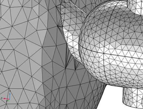
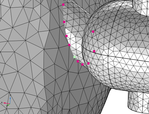
Click Center at Coordinates to zoom in on a reported problem coordinate to inspect the intersection more closely. If the mesh is more complex, it can help to also clip around the coordinates to remove everything except the mesh closest to the coordinates from the view and you can also rotate the mesh such that you see at least some of the reported points more clearly. Note that the list of reported points is filtered so that only a smaller number of intersecting elements are listed.
Union 1
As suggested in the Information node, use a mesh Union operation to compute the intersections.
1
In the Mesh toolbar, click  Booleans and Partitions and choose Union.
2
In the Settings window for Union, locate the Cleanup section.
3
From the Placement of mesh vertices list, choose Linear.
4
Click  Build Selected to unite the entire mesh using the default tolerance.
The union has partitioned the faces and the domains at the intersections. Along the new edges, some sliver triangles have been created. When building the physics-controlled mesh, the quality of the boundary mesh will be improved.
Next, build the physics-controlled mesh.
Physics-Controlled Mesh
1
In the Model Builder window, expand the Component 1 (comp1) > Meshes > Physics-Controlled Mesh node.
2
Right-click Physics-Controlled Mesh and choose Build All.
3
Click the  Transparency button in the Graphics toolbar.
4
In the Model Builder window, click Physics-Controlled Mesh.
You have now obtained a volume mesh for the combined vertebrae, discs, and pedicle screws.
 

1
The STL geometry is provided courtesy of Mark Yeoman, Continuum Blue, UK.