|
|
|
|
1
|
|
2
|
Click
|
|
1
|
|
2
|
|
3
|
|
1
|
|
2
|
|
3
|
|
1
|
|
2
|
|
3
|
Click
|
|
4
|
|
5
|
|
6
|
|
7
|
Locate the Boundary Selections section. In the table, enter the following settings:
|
|
1
|
|
2
|
|
3
|
|
4
|
|
1
|
|
2
|
|
3
|
|
4
|
|
5
|
|
6
|
|
1
|
|
2
|
|
3
|
|
1
|
|
2
|
|
3
|
Click
|
|
4
|
|
5
|
|
6
|
|
7
|
Locate the Boundary Selections section. In the table, enter the following settings:
|
|
1
|
|
2
|
|
3
|
Click Center at Coordinates.
|
|
1
|
|
2
|
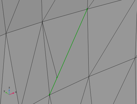
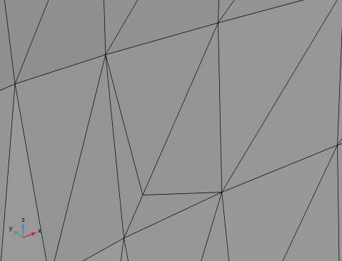
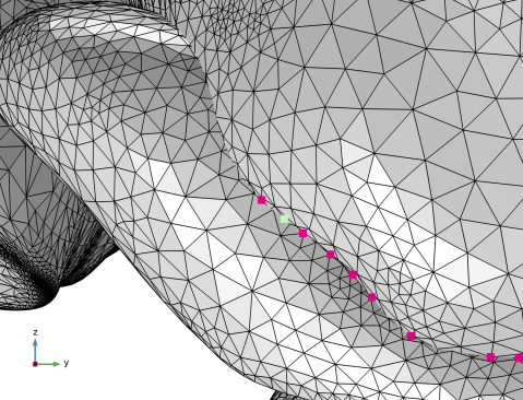
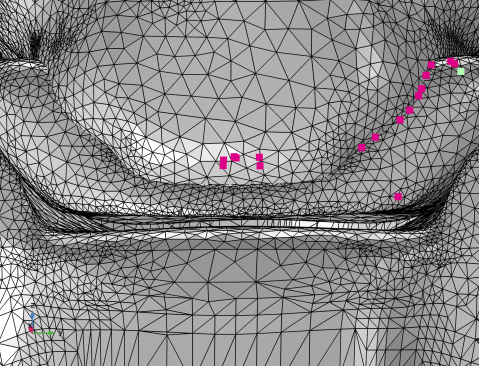
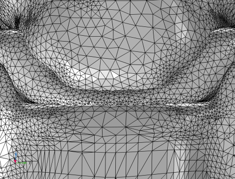
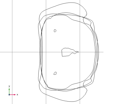
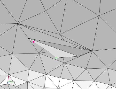
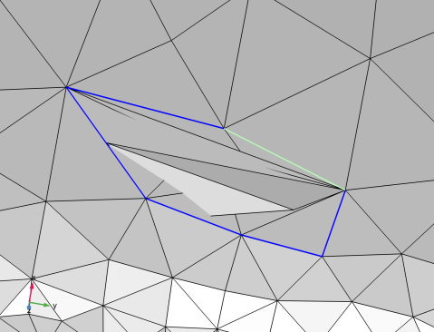
Select mesh edges around the intersecting elements by clicking them in the Graphics window, similar to what is shown in the image below. The selection is most easily done with transparency off. The selected edges can differ from the ones selected in the figure, as long as the edges form a closed loop, include the intersecting elements, and delimit only a small region around the intersecting elements. The last requirement is important when generating a new mesh face that follows the original mesh as close as possible.
 |
|
3
|
|
4
|
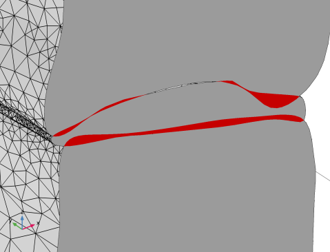
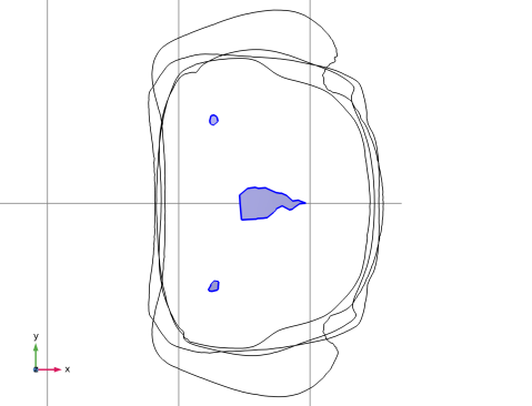
Select the Resulting small faces checkbox to create a selection containing the boundary with the intersecting elements.
|
|
5
|
Click
|
|
1
|
|
2
|
|
3
|
From the Selection list, choose Create Edges 1 (Small faces) (the boundary with the intersecting elements).
|
|
4
|
Click
|
|
1
|
|
2
|
|
3
|
|
4
|
|
5
|
|
6
|
Click
|
|
1
|
|
2
|
|
3
|
|
1
|
|
2
|
|
3
|
|
1
|
|
2
|
|
3
|
Click
|
|
4
|
|
5
|
|
6
|
|
1
|
In the Model Builder window, expand the Global Definitions > Mesh Parts > C4 > Import 1 > Information node, then click Information.
|
|
2
|
|
3
|
|
4
|
Click
|
|
1
|
|
2
|
|
3
|
|
4
|
|
5
|
|
6
|
Locate the Domain Selections section. In the table, enter the following settings:
|
|
7
|
Locate the Boundary Selections section. In the table, enter the following settings:
|
|
8
|
|
1
|
|
2
|
|
3
|
|
1
|
|
2
|
|
3
|
Click
|
|
4
|
|
5
|
|
6
|
Locate the Domain Selections section. In the table, enter the following settings:
|
|
7
|
Locate the Boundary Selections section. In the table, enter the following settings:
|
|
1
|
|
2
|
Click
|
|
3
|
|
4
|
|
5
|
|
6
|
Locate the Domain Selections section. In the table, enter the following settings:
|
|
7
|
Locate the Boundary Selections section. In the table, enter the following settings:
|
|
8
|
|
9
|
|
10
|
|
11
|
|
1
|
|
2
|
|
3
|
|
1
|
|
2
|
|
3
|
|
4
|
|
5
|
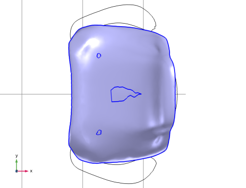
Select the Import unmeshed domains checkbox to also import the domain you created earlier for the volume enclosed by the mesh. Domains are needed for most physics interfaces when running simulations in the volumes inside.
|
|
6
|
Click Import.
|
|
1
|
|
2
|
|
3
|
|
4
|
|
5
|
Select the Import unmeshed domains checkbox.
|
|
6
|
Click Import.
|
|
1
|
|
2
|
|
3
|
|
4
|
|
5
|
|
1
|
|
2
|
|
3
|
|
4
|
|
5
|
Select the Import unmeshed domains checkbox.
|
|
6
|
Click Import.
|
|
1
|
|
1
|
|
2
|
|
3
|
|
4
|
|
1
|
|
2
|
|
3
|
|
4
|
|
5
|
Select the Import unmeshed domains checkbox.
|
|
6
|
Click Import.
|
|
1
|
|
2
|
|
3
|
Click Center at Coordinates.
|
|
4
|
|
1
|
|
2
|
|
3
|
|
4
|
|
5
|
Select the Import unmeshed domains checkbox.
|
|
6
|
Click Import.
|
|
7
|
|
8
|
|
9
|
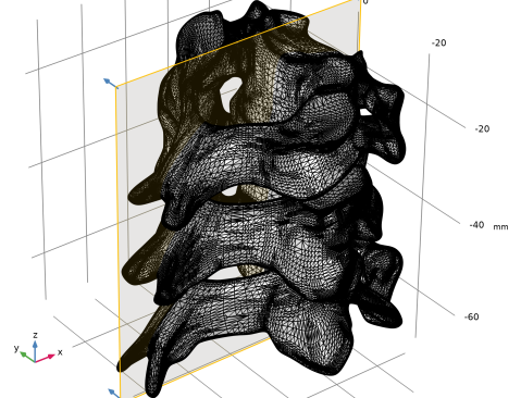
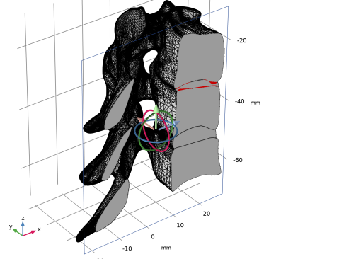
In the Graphics window, hover over the frame for plane1 and right-click to open up the Graphics context menu. Select Align to y-Axis to rotate plane1 to be parallel with the xz plane.
|
|
10
|
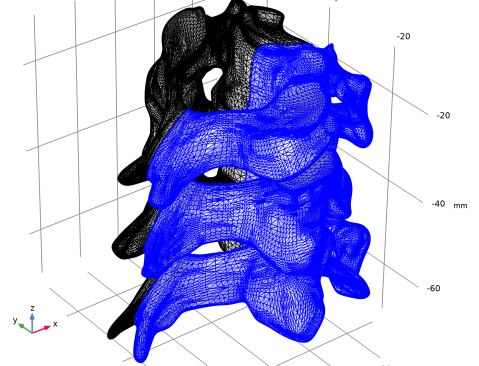
In the Graphics window, hover over the frame for plane1 and right-click to open up the Graphics context menu. Select Invert Clipping to view the part of the mesh that is positioned on the positive side of the y axis.
|
|
11
|
|
12
|
In the Graphics window toolbar, click
|
|
13
|
In the Graphics window toolbar, click
 |
|
1
|
|
2
|
|
3
|
|
5
|
|
6
|
|
7
|
|
8
|
|
1
|
Go to the Selection List window to verify that there are 7 domains in the mesh, one large domain for each of the imported meshes and two that have been created for the intersecting regions. Keep the window open as you will use it more later on.
|
|
1
|
|
3
|
|
4
|
|
5
|
|
6
|
|
7
|
|
1
|
|
2
|
|
4
|
|
1
|
|
2
|
|
3
|
|
5
|
Click
|
|
6
|
|
1
|
|
3
|
|
1
|
|
3
|
|
4
|
|
1
|
|
2
|
|
3
|
|
4
|
|
5
|
|
6
|
Click
|
|
1
|
|
2
|
|
3
|
|
4
|
Click
|
|
1
|
|
2
|
|
3
|
|
1
|
|
2
|
|
3
|
|
4
|
Click
|
|
1
|
|
2
|
|
3
|
|
4
|
|
5
|
Select the Import unmeshed domains checkbox to also import the domains formed in the Mesh Parts.
|
|
6
|
Click Import.
|
|
1
|
|
2
|
|
3
|
|
4
|
|
5
|
Click
|
|
6
|
|
7
|