|
|
|


|
1
|
|
2
|
In the Select Physics tree, select Acoustics > Pressure Acoustics > Pressure Acoustics, Frequency Domain (acpr).
|
|
3
|
Click Add.
|
|
4
|
Click
|
|
5
|
|
6
|
Click
|
|
1
|
|
2
|
|
1
|
|
2
|
|
3
|
|
4
|
|
5
|
Click to expand the Layers section. In the table, enter the following settings:
|
|
6
|
Clear the Layers on bottom checkbox.
|
|
7
|
Select the Layers on top checkbox.
|
|
1
|
|
2
|
|
3
|
|
4
|
|
5
|
|
6
|
Locate the Selections of Resulting Entities section. Select the Resulting objects selection checkbox.
|
|
1
|
|
2
|
|
3
|
|
4
|
|
5
|
Locate the Selections of Resulting Entities section. Select the Resulting objects selection checkbox.
|
|
1
|
|
2
|
|
1
|
|
2
|
|
3
|
|
1
|
In the Model Builder window, under Component 1 (comp1) > Pressure Acoustics, Frequency Domain (acpr) click Pressure Acoustics 1.
|
|
2
|
|
3
|
|
4
|
|
5
|
|
1
|
|
2
|
|
3
|
|
4
|
|
1
|
|
2
|
|
3
|
|
4
|
|
5
|
Click to expand the Element Size Parameters section. Locate the Element Size section. Click the Custom button.
|
|
6
|
Locate the Element Size Parameters section.
|
|
7
|
|
1
|
|
2
|
|
3
|
|
4
|
|
5
|
|
6
|
Locate the Element Size Parameters section.
|
|
7
|
|
1
|
|
2
|
|
3
|
|
4
|
Click
|
|
1
|
|
2
|
|
3
|
|
4
|
|
5
|
|
1
|
|
2
|
|
3
|
Click
|
|
4
|
|
5
|
|
6
|
|
7
|
Click Replace.
|
|
8
|
|
9
|
|
10
|
|
11
|
|
12
|
|
1
|
|
2
|
|
3
|
|
1
|
|
2
|
|
3
|
|
4
|
|
5
|
|
1
|
In the Model Builder window, under Results, Ctrl-click to select Acoustic Pressure (acpr) and Sound Pressure Level (acpr).
|
|
2
|
Right-click and choose Group.
|
|
1
|
|
2
|
|
3
|
|
4
|
|
5
|
In the text field, type hmax.
|
|
6
|
|
8
|
|
9
|
|
10
|
|
11
|
|
12
|
|
1
|
|
1
|
In the Model Builder window, under Component 1 (comp1) right-click Definitions and choose Variables.
|
|
2
|
|
3
|
|
4
|
|
5
|
Locate the Variables section. In the table, enter the following settings:
|
|
1
|
|
2
|
In the Settings window for Pressure Acoustics, type Pressure Acoustics (Design Domain) in the Label text field.
|
|
3
|
|
4
|
Locate the Pressure Acoustics Model section. From the Specify list, choose Bulk modulus and density.
|
|
5
|
|
6
|
|
1
|
|
2
|
|
3
|
Select the Modify model configuration for study step checkbox.
|
|
4
|
In the tree, select Component 1 (comp1) > Pressure Acoustics, Frequency Domain (acpr) > Pressure Acoustics (Design Domain).
|
|
5
|
Click
|
|
1
|
|
2
|
Go to the Add Study window.
|
|
3
|
|
4
|
Click the Add Study button in the window toolbar.
|
|
5
|
|
1
|
|
2
|
|
1
|
|
2
|
|
3
|
|
4
|
Click Add Expression in the upper-right corner of the Objective Function section. From the menu, choose Component 1 (comp1) > Definitions > comp1.obj - Objective Function - 1.
|
|
5
|
Locate the Objective Function section. In the table, enter the following settings:
|
|
6
|
Click Add Expression in the upper-right corner of the Constraints section. From the menu, choose Component 1 (comp1) > Definitions > Density Model 1 > Global > comp1.dtopo1.theta_avg - Average material volume factor.
|
|
7
|
Locate the Constraints section. In the table, enter the following settings:
|
|
8
|
|
9
|
|
1
|
|
2
|
|
1
|
|
2
|
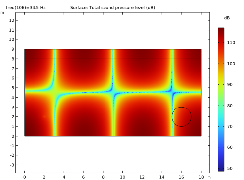
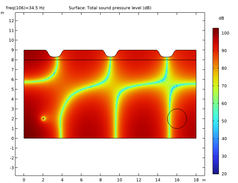
In the Settings window for Surface, click Replace Expression in the upper-right corner of the Expression section. From the menu, choose Component 1 (comp1) > Pressure Acoustics, Frequency Domain > Pressure and sound pressure level > acpr.Lp_t - Total sound pressure level - dB.
|
|
3
|
|
1
|
|
2
|
|
3
|
Select the Plot checkbox.
|
|
4
|
|
1
|
In the Model Builder window, expand the Study 2 > Solver Configurations > Solution 2 (sol2) > Optimization Solver 1 node.
|
|
2
|
|
3
|
|
4
|
|
5
|
|
6
|
|
7
|
Locate the General section. In the Variables list, choose Milling Material Volume Factor (comp1.dtopo1.theta_m1) and Acoustic Pressure (comp1.p).
|
|
8
|
|
9
|
In the Model Builder window, under Study 2 > Solver Configurations > Solution 2 (sol2) > Optimization Solver 1 > Stationary Solver 1 > Segregated 1 click Segregated Step 1.
|
|
10
|
|
11
|
|
12
|
In the Add dialog, select Milling Material Volume Factor (comp1.dtopo1.theta_m1) in the Variables list.
|
|
13
|
Click OK.
|
|
14
|
In the Model Builder window, under Study 2 > Solver Configurations > Solution 2 (sol2) > Optimization Solver 1 > Stationary Solver 1 > Segregated 1 click Segregated Step 2.
|
|
15
|
|
16
|
|
17
|
|
18
|
Click OK.
|
|
19
|
|
20
|
|
21
|
|
1
|
|
2
|
|
3
|
Click
|
|
5
|
|
6
|
Click to expand the Advanced Settings section. Select the Reuse solution from previous step checkbox.
|
|
7
|
|
1
|
|
2
|
Go to the Add Study window.
|
|
3
|
|
4
|
Click the Add Study button in the window toolbar.
|
|
5
|
|
1
|
|
2
|
|
3
|
Locate the Physics and Variables Selection section. In the Solve for column of the table, under Component 1 (comp1), clear the checkbox for Topology Optimization.
|
|
4
|
Click to expand the Values of Dependent Variables section. Find the Values of variables not solved for subsection. From the Settings list, choose User controlled.
|
|
5
|
|
6
|
|
7
|
|
8
|
|
9
|
|
10
|
|
11
|
Click Replace.
|
|
12
|
|
13
|
|
14
|
|
15
|
|
1
|
|
2
|
|
3
|
|
4
|
|
1
|
|
2
|
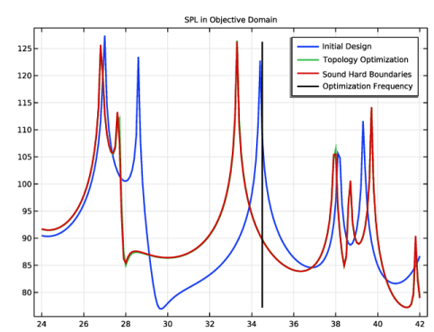
In the Settings window for Global, click Add Expression in the upper-right corner of the y-Axis Data section. From the menu, choose Component 1 (comp1) > Definitions > obj - Objective Function - 1.
|
|
3
|
Locate the y-Axis Data section. In the table, enter the following settings:
|
|
4
|
|
1
|
|
2
|
|
3
|
|
4
|
Locate the y-Axis Data section. In the table, enter the following settings:
|
|
1
|
|
2
|
|
3
|
|
4
|
|
5
|
Select the Use derivatives checkbox.
|
|
6
|
Click
|
|
7
|
|
1
|
|
2
|
Click Import.
|
|
3
|
Click
|
|
4
|
|
1
|
|
2
|
|
1
|
|
2
|
Go to the Add Physics window.
|
|
3
|
|
4
|
Find the Physics interfaces in study subsection. In the table, clear the Solve checkboxes for Study 1 - Initial Design, Study 2 - Topology Optimization, and Study 3 - Optimized Spectrum.
|
|
5
|
Click the Add to Component 2: Verification button in the window toolbar.
|
|
6
|
|
1
|
|
2
|
|
3
|
|
4
|
|
1
|
|
2
|
|
3
|
|
4
|
|
1
|
|
2
|
|
3
|
|
4
|
|
5
|
|
6
|
Locate the Element Size Parameters section.
|
|
7
|
|
1
|
|
2
|
|
3
|
|
4
|
Click
|
|
1
|
|
2
|
|
3
|
|
4
|
|
5
|
Locate the Expression section. In the Expression text field, type 0.5*realdot(p2,p2)/acpr2.pref_SPL^2.
|
|
1
|
|
2
|
Go to the Add Study window.
|
|
3
|
|
4
|
Find the Physics interfaces in study subsection. In the table, clear the Solve checkbox for Pressure Acoustics, Frequency Domain (acpr).
|
|
5
|
Click the Add Study button in the window toolbar.
|
|
6
|
|
1
|
|
2
|
|
3
|
Locate the Physics and Variables Selection section. In the Solve for column of the table, under Component 1: Optimization (comp1), clear the checkbox for Topology Optimization.
|
|
4
|
|
5
|
|
6
|
|
7
|
|
8
|
Click Replace.
|
|
9
|
|
10
|
|
11
|
|
1
|
In the Model Builder window, under Results, Ctrl-click to select Acoustic Pressure (acpr2) and Sound Pressure Level (acpr2).
|
|
2
|
Right-click and choose Group.
|
|
1
|
|
2
|
|
3
|
|
4
|
|
1
|
|
2
|
|
3
|
|
4
|
|
5
|
|
1
|
In the Model Builder window, under Results > Response Comparison right-click Global 2 and choose Duplicate.
|
|
2
|
|
3
|
|
4
|
Locate the y-Axis Data section. In the table, enter the following settings:
|
|
1
|
|
2
|
|
4
|
|
5
|
|
6
|
|
7
|
|
8
|