Use Partition by Expression (

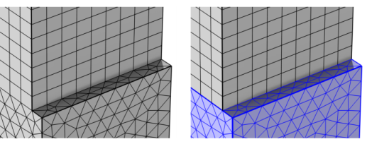
) to partition geometric entities of a mesh by creating at least one new geometric entity for the elements that fulfill the specified logical expression, as shown in
Figure 8-92.
To add a Partition by Expression node, select one or several entities in the
Graphics window, then choose one of the following:
Enter the properties for Partition by Expression using the following sections:
Enter a logical expression using x,
y, or
z (3D only); the mesh size
h and mesh quality
qual* (see
Mesh Element Quality);
Unary, Binary, and List Operators and Their Precedence Rules; and
Mathematical and Numerical Constants in the
Logical expression field. For instance, the expression
(x*x+y*y)<1 defines a ball partition in 2D and an infinite cylinder division in 3D. You can also use the Boolean variables
istri,
isquad,
istet,
ispyr,
isprism, or
ishex in the expression in order to partition the mesh according to the respective element type (triangular, quadrilateral, tetrahedral, pyramid, prism, or hexahedral, respectively). For instance, the expression
istet makes a separate domain for each connected set of tetrahedra, while the expression
ispyr || ishex makes a separate domain for each connected set of elements containing pyramids or hexahedra. You can also use the
meshelement variable to partition the mesh. For example, if you know that elements 1 to 10 are a separate domain, write
meshelement<=10 to partition this as a separate domain.
Use the Include element if expression is fulfilled for list to select the condition for which the logical expression is fulfilled for an element. Choose
All vertices to make an element satisfy the expression if it is true for all element vertices, or choose
Some vertex if it is true for at least one element vertex.
Select one or both of the Entities fulfilling expression and
Entities not fulfilling expression checkboxes to create predefined selections in subsequent nodes in the mesh sequence. To also make the selections available in all applicable selection lists outside the mesh sequence or mesh part (in physics and materials settings, for example), choose an option from the
Show in physics (
Show outside part if in a mesh part) list:
All levels,
Domain selection,
Boundary selection,
Edge selection or
Point selection. To keep the selection local to the mesh sequence or mesh part, choose
Off. The default is
Domain selection, which is suitable for use with materials and physics defined in domains. For use with a boundary condition, for example, choose
Boundary selection. These selections do not appear as separate selection nodes in the model tree. From the
Color list, choose a color for highlighting the resulting objects selection. See
Selection Colors and
Creating Named Selections in the Mesh Sequence.