Partition with Box
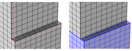
Use Partition with Box () to partition geometric entities of a mesh by creating at least one new geometric entity for the elements enclosed in the specified box, as shown in Figure 8-89.
Figure 8-89: Using a Partition with Box node (left) to define two domains in the imported hex mesh (right).
To add a Partition with Box () node, select one or several entities in the Graphics window, then choose one of the following:
Right-click in the Graphics window to open The Graphics Context Menu. Select Partition with Box () from the Booleans and Partitions menu.
Click Booleans and Partitions () on The Mesh Toolbar and select Partition with Box.
Right-click the Mesh node and select Partition with Box () from the Booleans and Partitions menu.
Enter the properties for the Partition with Box node using the following sections:
Then use the following sections to specify the geometric entities to partition, the properties of the box, and the condition for division:
Geometric Entity Selection
Define the geometric entities that you want to partition. You choose the geometric entity level from the Geometric entity level list:
Choose Entire geometry to divide all geometric entities according to the specified box.
Choose Domain, Boundary, or Edge to specify the domains, boundaries, or edges, respectively, that you want to partition or choose a named selection to refer to a previously defined selection. Use All domains, All boundaries, or All edges to select all entities of the specified dimension.
Box Limits
Specify the limits of the box in the x minimum, x maximum, y minimum, y maximum, z minimum (3D only), and z maximum (3D only) fields.
Condition
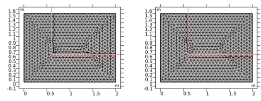
Use the Include element if box contains list to select the condition for which an element is enclosed in the specified box. Choose All vertices to consider an element to be enclosed in the specified box if all element vertices are inside, or choose Some vertex to consider it enclosed if at least one element vertex is inside the box, as shown in Figure 8-90.
Figure 8-90: Partitioning a mesh of a rectangle with x and y minimum set to 0.6 (pink lines) using different condition settings. The left image shows the result with Include element if box contains is set to All vertices. The right image shows the result with the condition set to Some vertex. The created edges follows the existing mesh edges.
Selections of Resulting Entities
Select one or both of the Entities inside and Entities outside checkboxes to create predefined selections in subsequent nodes in the mesh sequence. To also make the selections available in all applicable selection lists outside the mesh sequence or mesh part (in physics and materials settings, for example), choose an option from the Show in physics (Show outside part if in a mesh part) list: All levels, Domain selection, Boundary selection, Edge selection or Point selection. To keep the selection local to the mesh sequence or mesh part, choose Off. The default is Domain selection, which is suitable for use with materials and physics defined in domains. For use with a boundary condition, for example, choose Boundary selection. These selections do not appear as separate selection nodes in the model tree. From the Color list, choose a color for highlighting the resulting objects selection. See Selection Colors and Creating Named Selections in the Mesh Sequence.