Combining Geometry Objects
When combining several touching or overlapping geometry objects (see Figure 7-3) using the Boolean operations such as Union, and Compose, or if you partition an object using Partition Domains or Partition Objects, a single geometry object is created that is composed of different domains for each enclosed volume, as shown in Figure 7-4. This is also what happens when you build the Form Union node.
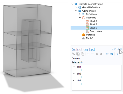
Figure 7-3: Left: Adding three overlapping blocks in turn to the geometry sequence. Right: The geometry sequence (top). The Selection List shows the block objects and their respective domains.
Figure 7-4: Left: Combining the three objects into one single object containing six domains.Right: The geometry sequence (top). The Selection List shows the domains in the union object (bottom).
It is also possible to combine objects of different types (solids, surfaces, curves, and points), as seen in Figure 7-5 and Figure 7-7. The object type is displayed in parenthesis beside the object tag in The Selection List Window (solid, surface, curve, point, or mixed).
Removing Interior Boundaries
Removing interior boundaries is good practice if the interior boundary is an effect of the geometry modeling and does not represent a border between different materials or between domains with different properties. When you remove the interior boundaries, the resulting geometry consists of fewer domains and puts fewer constraints on the mesh generation.
To remove interior boundaries, clear the Keep interior boundaries checkbox in a Boolean operations such as Union or Compose. You can also use the virtual operations Form Composite Domains, Ignore Faces (3D), and Ignore Edges (2D).
It is sometimes useful to keep interior boundaries for controlling the element size in the mesh. In such cases, use the virtual operations Ignore Faces (3D) and Ignore Edges (2D) and select the checkbox Keep input for mesh control, or use the mesh control operations Mesh Control Faces (3D) and Mesh Control Edges (2D). The interior boundaries are then not part of the geometry for defining physics nodes but are present during meshing to define areas where you want to use a finer element size, for example. See Controlling the Mesh Size Using Mesh Control Entities for more information.
Nonmanifold Objects
The most common example of a geometry object that has nonmanifold topology is the result of a Union operation: an object that contains interior boundaries and at least two domains, as shown in Figure 7-4. As Form Union creates a united object, the nonmanifold topology is commonly used in the software. In more detail, it means that a nonmanifold object in 3D that has at least one face contains one of the following configurations:
Figure 7-5: Left: Straps (dark gray) drawn as surfaces connected to the solid domain of a fuel tank. Right: The geometry of an RFID system containing isolated edges.
Figure 7-6: Left: An edge (blue) adjacent to four faces. Right: An edge (blue) interior to a face and adjacent to another face.
Figure 7-7: Left: Isolated vertices (red) used to simulate a microphone array inside the geometry of a car cabin. A boundary is hidden for viewing purposes. Right: A face that ends in the same vertex two times.
The definition of nonmanifold objects is analogous for curve objects in 3D as well as for objects in 2D and 1D.