Geometry Dimensions, Geometry Objects, and Geometric Entities
You can create model components with the following geometry dimensions: 3D, 2D, 2D axisymmetric, 1D, 1D axisymmetric, and 0D. A 0D component does not have a geometry and can therefore only be used for space-independent modeling such as ordinary differential equations, ODEs, and differential-algebraic equations, DAEs, where the dependent variables can depend on time. See also Choosing the Space Dimension.
For the 1D, 2D, and 3D dimensions, geometry objects are created using the Geometric Primitives and importing CAD data from file. The Geometry Operations can transform the objects, convert the object from one object type to another, and create a composite geometry object by forming unions, set differences, and set intersections of existing geometry objects. The object can be of the types solid, surface, curve, point, and mixed and are displayed beside the object name in The Selection List Window, as shown in Figure 7-1. It is also possible to check which objects are solid by adding a Clip Plane and select Show Cross Section. It is also possible to set to highlight object overlaps with a red color, as shown in Figure 7-1.
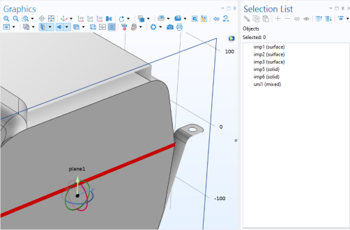
Figure 7-1: A clip plane showing the cross section of imported parts. With the setting Show Cross Section, it is possible to see that the top part is hollow. The overlap between two of the parts is selected to be highlighted in red.
The created geometry objects are united or assembled and then analyzed and divided into a finalized geometry that consists of geometric entities: domains, boundaries, edges, and points. The finalized geometry forms the basis for selecting geometric entities and then assigning and defining material properties, physics, and meshes. See The Form Union/Assembly Node — Uniting the Geometry for information about forming a union or an assembly with the created geometry as its input. See also Associative Geometry and Selections of Geometry Objects below.
Depending on the geometry dimension, different geometry entities represent domains and boundaries, for example, and some geometric entities are not applicable in all dimensions. See the following overview:
Figure 7-2: Geometric objects and the corresponding geometric entities for different geometry dimensions.
The finalized geometry consists of the following geometric entities:
Domains (where you can apply material properties, for example) in the finalized geometry are volumes in 3D, surfaces in 2D, and intervals in 1D.
Boundaries (where you can apply boundary conditions, for example) in the finalized geometry are surfaces in 3D, edges in 2D, and points in 1D.
Edges are only applicable for 3D geometries.
Points are only applicable for 2D and 3D geometries.