The Radiation Pattern Plots
The Radiation Pattern plots are available with this module to plot the value of a global variable (for example, the far field norm, normEfar and normdBEfar, or components of the far-field variable Efar).
The variables are plotted for a selected number of angles on a unit circle (in 2D) or a unit sphere (in 3D). The angle interval and the number of angles can be manually specified. For 2D Radiation Pattern plots, the reference direction from which the angle is measured and the normal to the plane the far field is computed for can also be specified. For 3D Radiation Pattern plots, you also specify an expression for the surface color.
The main advantage with the Radiation Pattern plot, as compared to making a Line Graph, is that the unit circle or sphere that you use for defining the plot directions is not part of your geometry for the solution. Thus, the number of plotting directions is decoupled from the discretization of the solution domain.
Default Radiation Pattern plots of the far-field norm are automatically added to any model that uses far-field calculation features combined with a far-field domain feature. If a model is driven by ports, an antenna realized gain plot is added instead. An Export Expressions subfeature is also added under the default Radiation Pattern node to include elevation and azimuth angle information. This subfeature is useful when performing Add Plot Data to Export from the context menu.
1See Directivity via Global Evaluation.
2See 3D Far-Field Norm Functions in 2D Axisymmetry.
3See Array Factor Operators.
4See Far-Field Analysis Using Functions and Operators.
Far-Field Analysis Using Functions and Operators
The postprocessing far-field functions are available under Component>Definitions>Functions. Below you find example models using these functions and some links to more information.
3D example with a Polar Plot Group Optical Scattering off a Gold Nanosphere: Application Library path Wave_Optics_Module/Optical_Scattering/scattering_nanosphere
Radiation Pattern in the COMSOL Multiphysics Reference Manual
3D Far-Field Norm Functions in 2D Axisymmetry
The functions norm3DEfar and normdB3DEfar calculate the 3D far-field norms, based on field solutions in 2D axisymmetric geometry. These functions are available in these cases:
The function can be used in a 3D Radiation Pattern plot, where the input argument of the function must be same as the Azimuth angle variable in the Evaluation section in the Settings window.
The suffix of a function name varies based on the circular port mode type, port mode number, and azimuthal mode number in the physics interface. For example, when using azimuthal mode number 1 in the physics interface and transverse electric (TE) mode with mode number 2 in the port settings, the generated operator name is norm3DEfar_TE12.
When the function is used in a radiation pattern plot under a 1D or a polar plot group, the value of input argument defines the plotting plane regardless of the normal and reference direction in the Evaluation section in the Settings window. For example, norm3DEfar_TE12(0)evaluates the norm of the electric far field for the TE12 mode for a 0-degree azimuthal angle. This is equivalent to plotting this variable on the xz-plane. Similarly, norm3DEfar_TE12(pi/2) is the evaluation at a 90-degree azimuthal angle, which is equivalent to plotting the variable on the yz-plane.
The 3D far-field norm, the linear superposition of the positive and negative azimuthal modes scaled by 0.5, is
,
where ϕ is the azimuthal angle.
Array Factor Operators
Uniform array factor
The equation for the uniform three dimensional array factor operator af3 is
,
´,
where θ is the elevation angle and ϕ is the azimuthal angle.
The uniform two-dimensional array factor operator af2 is simpler than the three-dimensional version, as the third, the z-component factor, is unity.
The number of input arguments for the array factor operators depends on the dimension of model component, 2D, 2D Axisymmetric, or 3D.
Hexagonal uniform array factor
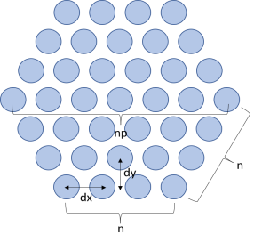
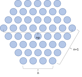
When array elements are distributed not on a conventional rectangular grid but on a triangular grid forming a hexagonal shape array, the two-dimensional afhex operator is available in a 3D model.
For an odd number of array elements, the number of elements on the diagonal axis is also an odd number. For instance, when np is set to 15, the number of elements, n, on a hexagonal array edge, (np + 1)/2, evaluates to 8 and the total number of array elements, 3n2 − 3n + 1, is then 169.
Figure 2-1: Configuration for an odd number hexagonal array.
For an even number of array elements, the number of elements on the diagonal axis is also an even number. The shape of the hexagon is uneven and configured with two edge sizes. The number of elements on the smaller edge n is np/2 and the other edge has n + 1 elements. When np is set to 8, the total number of array elements, 3n2, is 48.
Figure 2-2: Configuration for an even number hexagonal array.
Antenna Analysis Using Far-Field Variables
The directional properties of a radiation pattern described by variables, generated from a far-field calculation feature, help to characterize the performance of antenna devices.
Directivity from a 3D Plot
While plotting a 3D radiation pattern, the maximum directivity can be calculated by evaluating the ratio between the radiation intensity and the average value of the radiation intensity. Since the radiation intensity is a function of power, the square of the far-field norm has to be used in the Directivity expression in the Radiation Pattern settings window for the antenna directivity calculation. For other physics interfaces, such as in the Acoustics module, the expression is different.
Directivity via Global Evaluation
The maximum directivity can be computed through Results>Derived Values>Global Evaluation. This calculation is based on the maximum and averaged intensity values on the far-field calculation selection. It requires the selection for the far-field calculation feature to be spherical for 3D and circular for 2D axisymmetric model components, both centered at the origin.
Gain
The antenna realized gain is defined as
where U is the radiation intensity, , and Pin is the total input power.
The antenna gain is
where the delivered power, Pdelivered is Pin(1 − |S11|2). The gain is available only when the S-parameter calculation is valid, that is, for the single port excitation case.