Enclosed Fluids
Fluid loads are commonly encountered in structural analyses. When a closed cavity contains a fluid and the fluid velocity is not as important as the pressure load on the interior walls, the analysis can be simplified as compared to a full Fluid–Structure Interaction analysis. In this case, the fluid volume does not need a mesh.
The fluid load is modeled with a certain assumption about the fluid’s compressibility. For instance, it can be modeled as a compressible ideal gas, or as fully incompressible fluid. An extra equation of state is imposed with a weak constraint on the pressure variable.
This technique is useful for modeling rubber parts filled with air or other gases (seals, airbags, balloons), and also for pressure vessels and other fluid containers.
An enclosed cavity is defined by selecting boundaries, which must form a single, closed volume. A cavity may contain disconnected interior solids (which themselves may enclose cavities) as illustrated in the figure below. One Enclosed Cavity node can only represent a single cavity. If a models contains multiple cavities, add one Enclosed Cavity node for each individual volume.
Figure 3-46: A solid (gray) enclosing a cavity filled with a fluid (blue). All solid boundaries adjacent to the cavity (orange) define the volume of the cavity.
Here, a solid encloses a fluid, and additional solid particles are suspended inside the fluid, two of which enclose interior volumes. The primary cavity volume shown in blue, is defined by selecting all solid boundaries adjacent to the cavity. These boundaries, which include the boundaries adjacent to the solid particle boundaries, are highlighted in orange.
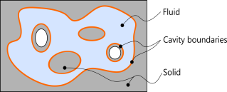
The enclosed volume is computed by defining a flux vector, which flows through all cavity surfaces. This flux is based on the position vector of the solid in its deformed and undeformed configuration. Using the divergence theorem the volume can be obtained from a surface integral.