Universal Joint Theory
An Universal Joint, also known as Hooke’s joint or Cardan joint, is commonly used to transmit rotational motion between shafts that have different orientations. Physically this joint is made up of a pair of hinge joints, oriented perpendicular to each other, connected by a cross shaft or gimbal. This joint is a kind of abstract joint where the gimbal is not modeled and both the shafts are directly connected to each other. In general, this joint is used to transfer mechanical power from one shaft to another shaft. The added degrees of freedom in this joint are the relative rotations about the two legs of the gimbal that form the joint axis and second axis.
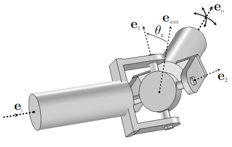
The following is an addition to the Prismatic Joint Theory, some of which is also applicable for the universal joint.
Joint Axis and Local Coordinate System
In this joint, the initial orientation of input and output shafts are based on user inputs. The initial auxiliary axis is defined as perpendicular to the plane spanned by the shafts:
If both the shafts have the same initial orientation, the initial output shaft orientation in this expression is replaced with an arbitrary axis, which is not parallel to the initial input shaft orientation.
You can also define the auxiliary axis explicitly. In this case, a projection is made in the plane perpendicular to the initial input shaft orientation to ensure the orthogonality of initial auxiliary axis and initial input shaft orientation.
The initial axis connecting the gimbal and input shaft or initial joint axis can be defined as being the same as the auxiliary axis
Alternatively, the initial joint axis can be defined by rotating the initial auxiliary axis (eaux0) about the initial input shaft orientation (ei0) with a specified angle (θg0):
The initial second axis and initial third axis are formed by
The rotated local coordinate system computed as
The current orientation of input and output shafts is computed by multiplying the initial directions with the corresponding rotation matrices:
Universal Joint Formulation
The formulation is similar to that of a hinge joint, except the definition of the relative quaternion, which is written as
where
Joint Elasticity in Universal Joint
The elastic degrees of freedom are written as
Postprocessing Variables
For the universal joint, some extra variables for use in postprocessing are defined.
Angular Velocity and Total Rotation of Input and Output Shafts
The angular velocities and total rotation for both input and output shafts are computed:
In order to evaluate the integrals, two extra ODE degrees of freedom are created for each universal joint.
Torsional Moment in the Shafts
The torsional moments in the input and output shafts are computed using
Angle Between Shafts
The angle between the shafts (bend angle) β is computed using