Physics and Variables Selection
The Settings window of all study steps generating equations contains a Physics and Variables Selection section. Here you can control which dependent variables to solve for and also disable individual nodes for the study step. This can be useful for:
By default, you can control which dependent variables to solve for in the study step. Solving can be enabled or disabled for entire physics interfaces and other high-level features. To disable individual physics features and other nodes in the Model Builder, or change equation and discretization settings for physics interfaces, select the Modify model configuration for study step check box (see Modifying the Model Configuration below).
Selecting Physics Interfaces to Solve For
The Physics interface column contains the names of entities defining dependent variables which can be disabled in the solvers. These include
By default, most studies solve for dependent variables for which there is a corresponding equation matching the study type. You can choose to not solve for one or more of the listed entities by clearing the  check box in the Solve for column. If a physics interface cannot set up an equation matching the study step type, the check box will be automatically cleared and disabled unless an equation form has been explicitly selected for the interface.
The dependent variables associated with a physics interface or functionality for which the Solve for check box is cleared are not solved for but still exist in the model. Their value after solving is controlled by the separate settings for values of variables not solved for (see Values of Dependent Variables).
If you do not want to create default datasets for components where all dependent variables have been disabled in the solvers, select the Add datasets only for components solved for check box under Dataset generation policy on the Results page in the Preferences dialog box.
Clearing the Solve for setting for a physics interface in a study does not mean that the physics interface is disregarded. The solver then does not include the DOFs in its assembled system, but all variables and shape functions in the physics interface are generated. If the values of variables not solved for are taken from the solution of another study step (see Values of Dependent Variables), then variables are generated for the equation form of that study step. Otherwise, they are generated for the physics interface’s default equation form.
The Equation form column shows the equation form that will be used when assembling equations. By default, it is decided automatically and shows Automatic (stationary) for a Stationary study step, for example. You can change the equation form by first selecting the Modify model configuration for study step check box (see Modifying the Model Configuration below).
Selecting Multiphysics Couplings to Solve For
The Multiphysics couplings column contains the names of all multiphysics couplings in the model. You can choose to not solve for one or more of the multiphysics couplings by clearing the  check box in the Solve for column (by default, a study step solves for all coupling features that recognize the study type). If you clear the Solve for check box, any equations and dependent variables that the multiphysics coupling adds are not included, but the multiphysics coupling still affects the definition of variables.
Clearing the Solve for setting will for some multiphysics couplings remove the coupling effect from the model, for others it will not. This depends on whether the coupling is implemented as a separate equation added to the system — in which case it will me removed — or as a contribution to variables declared by the coupled physics interfaces — in which case it will be unaffected.
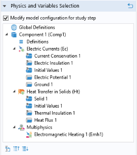
To ensure that the effect of a multiphysics coupling is completely disregarded, select the Modify model configuration for study step check box and disable it in the study step, or disable it manually in the Model Builder.
Solve-For State Icons
The leftmost column shows an icon that represent the state of the corresponding physics interface, multiphysics coupling or other entity:
Reduced-Order Models and Reconstruction
If the model contains a reduced-order model node under Global Definitions>Reduced-Order Modeling that has output variables and has Use output dependent variables enabled, there is also a table with a Reduced-order model column. Select the Store output dependent variables check box to store the output from the reduced-order model in a dependent variables for postprocessing every time a solution vector is written to the solution.
If a physics interface is not solved for in the study step while at the same time there is at least one reduced-order model under Global Definitions>Reduced-Order Modeling capable of reconstructing physics interface’s dependent variables, then there will be an additional table allowing you to choose a reconstructing reduced-order model. The Reconstruction column lists all currently not solved for physics interfaces for which there is at least one reconstructing reduced-order model. The Reduced-order model column offers a choice for each physics interface between the available reconstructing reduced-order models, or None, which is the default.
By default, a selected reduced-order model applies to all fields and states in the physics interface. If desired, it is possible to use different reconstruction for different fields and states by choosing another Reduced Model node in the Field and State nodes.
Modifying the Model Configuration
If the Modify model configuration for study step check box is selected, you can modify the model configuration in a number of ways in addition to specifying what to solve for. The Physics and Variables Selection section then contains a tree that is a copy of the main Model Builder tree but filtered to only show nodes that allow some form of modification. Depending on the type of node selected in the tree, you can:
Disable control over a frame implemented by a node, available for Moving Mesh, Deformed Geometry, Shape Optimization, and some physics interfaces.
Figure 20-4 contains an example of what the tree view may look like. Select one or more nodes in the tree and right-click or use the buttons at the bottom of the section (below the tree) to change their status. Click the Go to Source button () to move to the corresponding original node in the model tree. Click the Collapse All () and Expand All () buttons if desired to completely collapse or expand the physics tree. Depending on the selected nodes, additional actions appear in the toolbar and context menu.
Figure 20-4: An example of a Physics and Variables Selection section tree when the Modify model configuration for study step check box is selected.
Disabling and Enabling Nodes
Click Disable (or right-click to select it from the context menu) to disable enabled nodes that are possible to disable. The contributions, conditions, or variables in a node that you disable are not included in the study when solving. A disabled node is unavailable in the tree. You can also right-click any applicable node in the model tree to select Disable in all studies. That node is then disabled for all studies.
Click Enable (or right-click to select it from the context menu) to enable disabled nodes. The contributions, conditions, or variables in a node that you enable are included in the study when solving.
When you right-click, the following context menu options mean that a node cannot be enabled or disabled:
Cannot be Disabled — for default nodes in the physics interfaces.
Disabled in Model Builder — for nodes that you have disabled in the Model Builder.
When solving, equations and variables are generated as if the disabled nodes in the tree were disabled in the Model Builder. This means that the nodes’ selections override each other as if the nodes were disabled in the Model Builder.
Options for Discretization and Equation Form for the Main Physics Interface Nodes
The following options are available for the main physics interface nodes under the Physics and Variables Selection tree for modifying the discretization and the equation form:
From the Discretization list, choose a discretization for the physics in the physics interface. The default (and often the only) choice is Physics settings, which means that the study uses the discretization from the main physics interface node’s settings. Changing it affects the discretization order used by this study. To add another discretization, use a separate Discretization node in the physics interface.
From the Equation form list, choose an applicable equation form for the study step and physics interface: Automatic (the default, appearing with the default equation form in parentheses such as Automatic (Stationary)) or any other applicable equation form. If you change the equation form, the information is updated in the table of physics interface when you clear the Modify model configuration for study step check box. In addition to physics interfaces, the Equation form list is available for reduced-order models with a stateful interface.
Options and States for Nodes With Degrees of Freedom
Nodes that define dependent variables allow, in addition to complete disabling, a choice between solving and not solving for their degrees of freedom. Right-click a node and select one of the following from the context menu, or click the button beneath the tree. Selecting these options generally affects all its children in the tree. Select:
Solve For (the default setting) to fully enable the node and solve for dependent variables defined by the node and its active children. This is similar to the check boxes in the Solve for columns when not using Modify model configuration for study step. A physics interface in this state shows a small green dot in its lower-right corner to indicate that the study step solves for the degrees of freedom (dependent variables) in the physics interface and features. This is an example of a Laminar Flow interface with the green dot: .
Disable in Solvers to not solve for the physics interface but provide degrees of freedom (dependent variables) and other physics node variables using the settings for values of variables not solved for (see Values of Dependent Variables). This state is similar to when a corresponding Solve for column check box is cleared when not using Modify model configuration for study step. A physics node in this state shows a small orange dot in its lower-right corner to indicate that the node and its active children provide degrees of freedom but these are not solved for in the study step. For example, a Laminar Flow interface with an icon that looks like this is both showing that it provides degrees of freedom not solved for (orange dot in the lower-right corner) and has a change of state indicated by the asterisk.
Disable in Model to fully disable a node and its children in the model. The node and its children do not contribute to the study, and no variables, including the degrees of freedom (dependent variables), are included. A disabled node and its children are grayed out, and the parent node shows a small red dot in its lower-right corner to indicate that the study step provides no degrees of freedom for it. For example, a Transport of Diluted Species interface with an icon is disabled (grayed out), provides no degrees of freedom (red dot in the lower-right corner), and has a change of state indicated by the asterisk.
In addition, this type of nodes can be in the following states:
If the node is disabled in the Model Builder, it is grayed out. If you right-click it, the context menu contains Disabled in Model Builder. In this case, none of the options above are available.
If the node defines degrees of freedom but not equations applicable for the current study step type, then the Solve For option is grayed out and unavailable. Disable in Solvers is then the default option and therefore does not display any asterisk as indication of a changed state.
Change of States and Override and Contribution Indicators
An asterisk displays in the upper-right corner of nodes in the Physics and Variables Selection tree for which the state has been changed in some study step’s settings, including being disabled in either solvers or model. This mirrors the node in the main Model Builder tree. In general, any variable or physics node in the Model Builder that is disabled in any study step gets an asterisk in the upper-right corner. For nodes defining degrees of freedom, this applies also when you have not selected the Modify model configuration for study step check box and the check box in a Solve for column in the Physics and Variables Selection section has been cleared.
The dynamic visual icon indicators for overridden and contributing nodes also appear in the tree in the Settings window for the study steps when you have selected the Modify model configuration for study step check box in a study step’s Settings window. When you select a physics node in the tree, the override and contribution icon indicators appear in the same way as in the Model Builder when you select a physics node, but if you disable any physics node in the study step’s tree, the icon indicators then show how the physics node overrides and contributes to the model when one or more physics nodes are disabled in the study step.
Frame Control for Mesh Deformation
Multiple physics interfaces or other entities controlling the same frame are not allowed on the same selection. It is, however, possible to use multiple frame-controlling entities with overlapping selection, but you then have to explicitly disable frame control on all but one of these. You can choose different entities to control the frame in different study steps. In the Modify model configuration for study step tree a frame-controlling node has a label that is extended with the text Controls spatial frame or Controls material frame. Toggle the frame control on those nodes by selecting them in the tree and toggling the Control Frame Deformation button () in the toolbar or by right-clicking the node and selecting Control Frame Deformation from the context menu.
If you have the AC/DC Module, see Electric Shielding: Application Library path ACDC_Module/Introductory_Electric_Currents/electric_shielding.