Branches and Subbranches in the Tree Structure
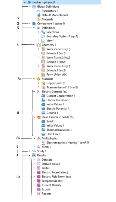
You can proceed through your modeling in the Model Builder by selecting the branches in the order suggested by the default positions, from the top down, or selecting and defining each branch as needed. One level below the main Component branch are subbranches as described in
Table 3-2
and shown in
Figure 3-2
. The node appearance can also change depending on many factors. See
Dynamic Nodes in the Model Builder
for examples.
Table 3-2:
The Model Builder Branches and Subbranches.
Figure Ref.
Icon
Name
Description and Link to More Information
Main Branches
1
Global Definitions
Define global parameters, and right-click to define global Variables, Functions, Load and Constraint Groups, a Materials branch, and optional Geometry Parts. Mesh Parts, and Extra Dimension branches, which are globally available in all model components. See
The Global Definitions Node
.
2
Various
Component
This branch includes the subbranches Definitions, Geometry, Materials, physics interfaces, and Mesh. You can also right-click the node to Add Physics and Add Mesh at this level. See
The Component Node
.
3
Study
This subbranch is where you set up study steps and solver configurations to solve a model using one or more study types for different analyses. See
Studies and Solvers
.
4
Results
The features contained in the subbranches for Datasets, Derived Values, Tables, Export, and Reports are used to present and analyze results. See
Results Analysis and Plots
.
Subbranches
5
Definitions (Local)
This subbranch is used to create Variables, Functions, Selections, Coordinate Systems, Nonlocal Couplings, and Probes as well as other definitions that are local to a specific component in your model. See
Global and Local Definitions
.
6
Geometry (Local)
This branch contains the definition of the model’s geometry, where you can import a geometry or build one yourself using the available tools. See
Geometry Modeling and CAD Tools
.
7
Materials (Global)
This branch makes it possible to add materials and a material switch for material sweeps at the global level. You can add materials in the same way as you do under a Component branch, but materials on the global level are available throughout the model and therefore have no Geometric Entity Selection section. See
Global Materials
.
7a
Materials (Local)
Collect all material properties organized in Material nodes with a defined geometric scope. Material properties required by any of the physics interfaces and features show up automatically in the defined material’s Settings window. See
Materials
.
8
Various
Physics interfaces
Each physics interface forms its own branch based on the model definition requirements. See
The Physics Interfaces
and
Creating a New Model
to start.
8a
Multiphysics
This is a main branch but is associated directly with the physics interface branches above it. It contains multiphysics coupling nodes. See
The Multiphysics Branch
.
9
Mesh
This subbranch collects all meshes defined for a model. If there is only a single mesh in a model, its Mesh node appears directly under the corresponding Component node. See
Meshing
.
10
Datasets
Datasets
refer to the source of data for creating Plots and Reports. It can be a Solution, a Mesh, or some transformation or cut plane applied to other datasets; that is, you can create new datasets from other datasets.
Views
If enabled in the Show More Options dialog box, you can add extra views for postprocessing purposes here. See
User-Defined Views
.
Derived Values
Used to define evaluations of numerical results — globally, in a point, or integrated quantities. For 2D and 3D plots, you can also get numerical results directly in a table by clicking the plot. See
About Derived Values
.
Tables
This subbranch displays the results from integral and variable evaluations defined in Derived Values nodes or by probes and stored in Table nodes. See
The Table Window and Tables Node
.
Color Tables
Used to define new color tables for use in the model. See
Custom Color Tables
.
Various
Plot Groups
After adding a 3D, 2D, or 1D Plot Group, plots are added and defined under this subbranch. See
Plot Groups and Plots
.
Evaluation Group
After adding an Evaluation Group, you can add evaluation features under this subbranch. See
About Evaluation Groups
.
Export
After a model is completed, you can add various components to this and then generate outputs (animations, data, images, or export), or export the information to your computer as image, movie, or data files for use in external documents or for other purposes. See
Export Types
.
Reports
This subbranch opens the Report Generator, which is a tool for reporting and documenting models created in COMSOL. It creates a record of the entire model including all the settings made during the modeling process. The report is an overview of the model and includes model properties, geometry, physics interfaces and features, mesh, studies, and results and visualization. See
Reports and Presentations
.
Figure 3-2:
An example of the Model Builder tree structure showing the many different types of branches and subbranches available in a model. Refer to
Table 3-2
to learn more about a node. Use the numbers to locate the node in the table.