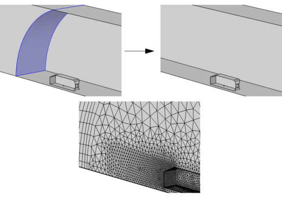
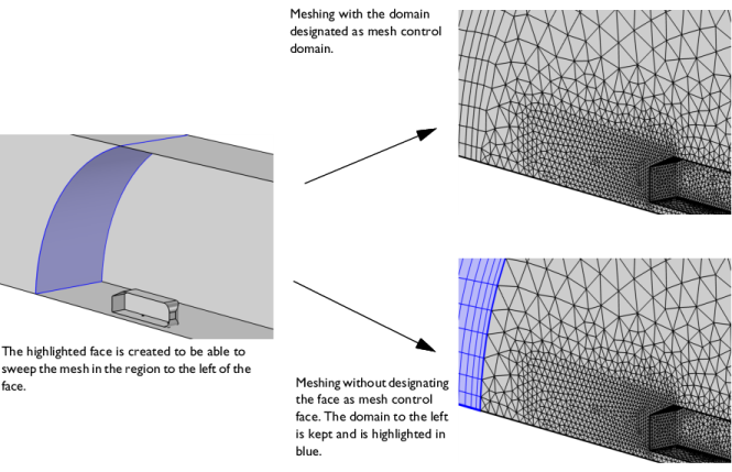
Use Mesh control faces for precise control of the mesh in specific regions of the geometry, without affecting the geometry used for assigning physics.
The operation removes the selected faces that are isolated or are located between two domains by ignoring them and composing the adjacent domains as shown in Figure 7-42 and
Figure 7-43. The faces become available when you build the mesh. This makes it possible to partition a domain to prepare it for swept meshing, or to control the mesh size in a specific region, without modifying the geometry that appears when assigning physics settings.
To use the operation, in the Geometry toolbar, from the
Virtual Operations menu (

), select
Mesh Control Faces (

). Then enter the properties of the operation using the following sections:
Select the faces that you want to use for mesh control in the Graphics window. They then appear in the
Face to include list. If the geometry sequence includes user-defined selections above the
Mesh Control Faces node, choose
Manual to select faces, or choose one of the selection nodes from the list next to
Faces to include.
Click the Active button to toggle between turning ON and OFF the
Faces to include selections.
Use the Include adjacent vertices and edges check box to specify if the operation also includes the ignorable vertices and edges adjacent to of the faces.