You are viewing the documentation for an older COMSOL version. The latest version is
available here.
Use the Lumped Port node to apply a voltage or current excitation of a model or to connect to a circuit. A lumped port is a simplification of the port boundary condition.
A Lumped Port condition can only be applied on boundaries that extend between two metallic boundaries — that is, boundaries where
Perfect Electric Conductor,
Impedance Boundary,
Transition Boundary, or
Layered Transition Boundary (Electromagnetic Waves, Frequency Domain interface only) conditions apply — separated by a distance much smaller than the wavelength.
Enter a unique Lumped port name. It is recommended to use a numeric name as it is used to define the elements of the S-parameter matrix and numeric port names are also required for port sweeps and Touchstone file export (for the Electromagnetic Waves, Frequency Domain interface).
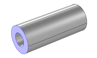
Select a Type of lumped port —
Coaxial,
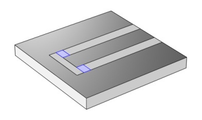
Multielement uniform,
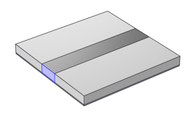
Uniform,
User defined, or
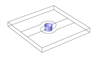
Via.
Select User defined for nonuniform ports, for example, a curved port and enter values or expressions in the fields —
Height of lumped port hport (SI unit: m),
Width of lumped port wport (SI unit: m), and
Direction between lumped port terminals ah. In 2D axisymmetry,
Coaxial does not support a nonzero azimuthal mode number. The
Azimuthal mode number should be set to zero in the
Out-of-Plane Wave Number section in the settings for
The Electromagnetic Waves, Frequency Domain Interface. When it is modeled in 3D, its geometry has to be a full coaxial shape.
|
|
Notice that the input field for Direction between lumped port terminals ah is not shown in 2D, when Electric field components solved for is set to Out-of-plane vector in the Components section for the physics interface. In this case the Direction between lumped port terminals ah is defined to be in the out-of-plane direction.
|
Select Multielement uniform for multiexcitation or termination of, for example, a coplanar waveguide port or a differential port. The direction of the field in each sub-element of the
Multielement uniform lumped port is defined by the subnodes,
Uniform element.
Select Via for excitation or termination of a cylindrical shape of a structure used in a metalized via that is a plated through hole.
Select a Terminal type — a
Cable port for a voltage driven transmission line and S-parameter calculation, a
Current driven port, or a
Circuit port.
For Cable, select
On or
Off from the
Wave excitation at this port list to set whether it is an inport (excitation) or a listener port (observation).
If On is selected for the
Wave excitation at this port, select
Voltage or
Power from the
Source type. For the
Voltage source type, enter a
Voltage V0 (SI unit: V), and
Port phase θin (SI unit: rad). For the
Power source type, enter a
Power P0 (SI unit: W) that is the average input power to the lumped port.
Note it is only possible to excite one Cable port at a time if the purpose is to compute S-parameters. In other cases, for example, when studying microwave heating, more than one inport might be wanted, but the S-parameter variables cannot be correctly computed so if several ports are excited, the S-parameter output is turned off.
For the Electromagnetic Waves, Frequency Domain and Microwave Heating interfaces, the Port Sweep Settings cycles through the ports, computes the entire S-matrix, and exports it to a Touchstone file. When using port sweeps, the local setting for
Wave excitation at this port is overridden by the solver so only one port at a time is excited.
No entry is required if a Circuit terminal type is selected above.
|
•
|
For a Cable terminal type enter the Characteristic impedance Zref (SI unit: Ω). When using a lumped port on a partial geometry combined with symmetry plane features, enter the value for the full geometry if the Characteristic impedance adjustment by symmetry plane check box is marked.
|
|
•
|
For a Current terminal type enter a Terminal current I0 (SI unit: A).
|
Enter a Relative permittivity (default is 1) for the dielectric material between the coaxial inner and outer conductor and then click the
Compute Coaxial Line Impedance button to compute the impedance for the coaxial lumped port. The result is displayed in the
Messages window.
The Calculate S-parameter check box needs to be selected for S-parameter calculation with the Electromagnetic Waves, Transient and Electromagnetic Waves, Time Explicit interfaces, while the
Cable port in the Electromagnetic Wave, Frequency Domain calculates S-parameters automatically.
When Calculate S-parameter is selected, select
Voltage source type from the list (default
Modulated Gaussian pulse). The
Modulated Gaussian pulse is defined as
where the Center frequency f0 defines the location as 2
/f0, the standard deviation as 1/(
2f0), and the modulation frequency
f0.
ηf is the upshift ratio for the sinusoidal modulation frequency.
When Calculate S-parameter is selected, enter a
Center frequency f0 for the input modulated Gaussian pulse (SI unit: Hz).
When Calculate S-parameter is selected, enter a
Modulation frequency upshift ratio ηf for the input modulated Gaussian pulse.
|
|
As a multiport device example, Branch-Line Coupler: Application Library path RF_Module/Couplers_and_Power_Dividers/branch_line_coupler
For example of how to use the Multielement uniform lumped port, Coplanar Waveguide Bandpass Filter: Application Library path RF_Module/Filters/cpw_bandpass_filter
|
In the Electromagnetic Waves, Transient interface, when Terminal type is set to
Current, select
Current Pulse Type from
User defined,
Electrostatic discharge, and
Lightning.
Enter pulse model parameter values and click the Plot Pulse Shape button to inspect the current pulse instantly as a function of time before running a simulation.
When Current Pulse Type is set to
Electrostatic discharge, select
Electrostatic Discharge Pulse Model from
Human body model,
Extended human body model,
Machine model, and
Charged device model.