Particle Beam
Use the Particle Beam node to release a nonlaminar beam of particles normal to a boundary with a specified distribution in phase space.
The Nonlocal Accumulator subnode is available from the context menu (right-click the parent node) or from the Physics toolbar, Attributes menu.
For 2D axisymmetric models, always select the Include out-of-plane degrees of freedom check box in the physics interface Advanced Settings section when modeling particle beams, since the out-of-plane position and velocity are crucial in ensuring that the released beam has the specified emittance and other beam parameters.
Go to Release for information about the following sections: Release Times, Release Current Magnitude, Released Particle Properties, Initial Value of Auxiliary Dependent Variables, and Advanced Settings.
Initial Position
Enter the Number of particles per release N (dimensionless). The default is 1000.
Select a Beam position: From coordinates (the default), Centroid of selection, or Selected point. This option determines how the position of the center of the beam is computed. For 2D axisymmetric model components, an additional option is available, Axis of symmetry (the default).
For From coordinates enter coordinates for the Beam center location rc (SI unit: m). When Selected point is selected, the Reference Point Selection section is shown. Add at least one point to the selection to specify the center of the beam.
Initial Transverse Velocity
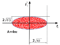
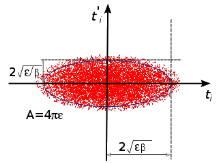
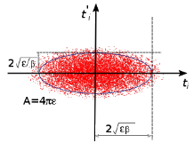
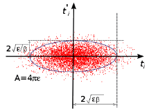
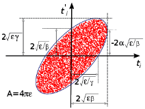
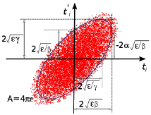
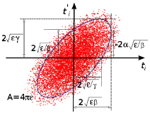
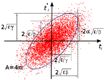
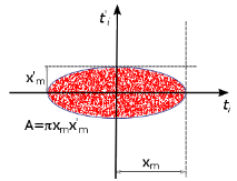
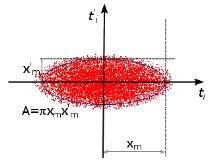
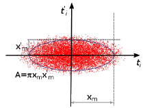
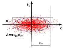
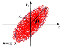
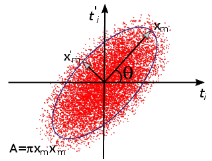
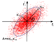
The Equation section of the Particle Beam feature contains images indicating how the phase space ellipses are constructed for the different settings available. To enable this, use Show>Equation Sections in the Model Builder toolbar.
Select a Sampling from phase space ellipse: KV, Waterbag, Parabolic, or Gaussian (the default).
-
The KV distribution places particles uniformly on the surface of a hyperellipsoid in 4-dimensional phase space. In 3D, this results in a particle distribution which is uniform in physical space, that is, the distance between particles is roughly the same throughout the beam cross-section.
-
The Waterbag distribution places particles uniformly inside the volume of a hyperellipsoid in 4-dimensional phase space. This yields a distribution in physical space in which particles are placed preferentially toward the center of the beam.
-
The Parabolic distribution is similar to the Waterbag distribution, but more particles are placed toward the center of the beam in physical space.
-
The Gaussian distribution fills the volume of a hyperellipsoid with a normal distribution density profile in 4-dimensional phase space. Similar to the Waterbag and Parabolic distributions, particles are preferentially placed closer to the center of the beam, although in this case, some particles can be placed a significant distance from the center
In 3D, select a Beam symmetry: Symmetric (the default) or Asymmetric. If Asymmetric is selected, two different sets of beam parameters, such as emittance and Twiss parameters, can be specified for the two transverse directions. If Symmetric is selected, the same beam parameters are used for both transverse directions.
Select a Beam orientation: Upright (the default) or Not upright. Upright means that the semimajor and semiminor axes of the phase space ellipses are parallel to the phase space coordinate axis. For a beam that is not subjected to any forces, Upright means that the beam is released at the location of the beam waist. Not upright allows the phase space ellipse to be rotated about its centroid.
Select a Transverse velocity distribution specification: Specify emittance and Twiss parameters (the default) or Specify phase space ellipse dimensions. Twiss parameters are generally favored by accelerator physicists, as they provide a standard method of defining the geometric properties of the phase space ellipse. Specifying phase space ellipse dimensions is often favored by spectrometer designers, as it allows the dimensions of the phase space ellipse and rotation angle to be specified directly.
In some cases it is possible to specify the Brightness B (SI unit: A/m2) instead of emittance. The default value is 1 mA/m2. The beam emittance is then computed from the brightness and the specified Release current magnitude. It is possible to enter a value or expression for the brightness of the beam if the following conditions are met:
-
-
Specify current is selected from the Particle release specification list in the physics interface Particle Release and Propagation section.
-
Symmetric is selected from the Beam symmetry list.
-
Specify emittance and Twiss parameters is selected from the Transverse velocity distribution specification list.
-
Specify brightness is selected from the Emittance specification list, which is only shown if the preceding conditions are met.
For 3D components, when the Beam symmetry is set to Asymmetric, it is possible to specify different phase space distributions in two orthogonal transverse directions. To decide how these transverse directions are oriented, select a Transverse direction specification: User defined or Parallel to reference edge. When Parallel to reference edge is selected, the Reference Edge Selection section is shown. Add an edge to this selection to define the coordinate system with respect to which the beam emittance and Twiss parameters are defined. Quantities with subscript 1 (εrms,1, β1, and so on) are used to determine the distributions of the position and velocity components parallel to the selected edge. Quantities with subscript 2 correspond to the position and velocity components perpendicular to the selected edge and to the direction of beam propagation. If User defined is selected, enter components of the Transverse beam direction t1 (dimensionless) directly. The default is the positive y direction.
Depending on the options selected above, it is possible to enter values for different physical quantities which describe the phase space ellipse dimensions. These are summarized below and in the following table:
The Twiss parameter beta β (SI unit: m). The default value is 1 m. The product of this and the emittance give an indication of the transverse size of the particle beam. For a given value of the beam emittance, increasing β causes the particle distribution in transverse position space to be broadened and the distribution in transverse velocity space to be tightened.
The 1-RMS beam emittance εrms (SI unit: m). The default is 1 mm. The emittance is a measure of the average spread of the particles in phase space. Qualitatively, a larger emittance means that the area occupied by the distribution of particles in phase space is larger.
The Brightness B (SI unit: A/m2). The default is 1 mA/m2. For symmetric beams the brightness can used instead of specifying the emittance. This option is only available when a certain combination of settings are applied, as explained in the previous list.
The Twiss parameter alpha α (dimensionless). The default is 0. When this value is nonzero, the phase space ellipse becomes rotated about the position-velocity axis. When Upright is selected from the Beam orientation list, α = 0. The remaining Twiss parameter γ (SI unit: 1/m) is not specified because it is derived from α and β.
The Maximum transverse displacement xm (SI unit: m). The default is 0.1 m. Typically, this value should be the same as the initial beam radius.
The Maximum relative transverse velocity xm' (dimensionless). The default is 0.04. Larger values indicate that the particles will have higher velocities in the transverse direction with respect to the longitudinal direction.
The Rotation angle θ (SI unit: rad). The default is 0. This rotates the phase space ellipse about the position-velocity axis.
Two separate values for all of the above options can be entered in 3D when the Beam symmetry is set to Asymmetric.
 
β, εrms
β, B
β, εrms
β, B
β, εrms
β, B
β, εrms
β, B
β, εrms, α
β, B, α
β, εrms, α
β, B, α
β, εrms, α
β, B, α
β, εrms, α
β, B, α
xm, xm
xm, xm
xm, xm
xm, xm
xm, xm’, θ
xm, xm’, θ
xm, xm’, θ
xm, xm’, θ
Initial Longitudinal Velocity
Select a Longitudinal velocity specification: Specify kinetic energy (the default) or Specify velocity. This determines the physical quantity of the remaining inputs in this section, which are used to initialize the longitudinal component of the particle velocity. Select a Longitudinal velocity distribution: None (the default), Normal, Uniform, or List of values. The following options are available.
For None, enter either a Kinetic energy E (SI unit: J), default 1 eV or a Velocity magnitude V (SI unit: m/s), default 1 m/s. This option releases one particle for each initial position.
For Normal, enter either a Mean kinetic energy Em (SI unit: J), default 1 eV and a Kinetic energy standard deviation σ (SI unit: J), default 0.1 eV, or a Mean velocity magnitude Vm (SI unit: m/s), default 1 m/s and Velocity magnitude standard deviation σ (SI unit: m/s), default 0.1 m/s. In both cases, also enter the Number of velocity values. The default is 1, and this option determines the number of particles released for each initial position, meaning this value multiplies the total number of particles released. The longitudinal component of the velocity is sampled from a normal distribution, meaning that roughly 68% of the particles will have an initial velocity within one standard deviation, and 95% within two standard deviations.
For Uniform, enter either a Minimum kinetic energy Emin (SI unit: J), default 1 eV and a Maximum kinetic energy Emax (SI unit: J), default 2 eV, or a Minimum velocity magnitude Vmin (SI unit: m/s), default 1 m/s and Maximum velocity magnitude Vmax (SI unit: m/s), default 2 m/s. In both cases, also enter the Number of velocity values. The default is 1, and this option determines the number of particles released for each initial position, meaning this value multiplies the total number of particles released. The uniform distribution will always include the minimum and maximum velocity or energy values if the Number of velocity values is greater than 1. If the Number of velocity values is 1, the velocity magnitude is simply the mean of the minimum and maximum values.
For List of values, enter either a list of Kinetic energy values (SI unit: J) or a list of Velocity values (SI unit: m/s). The length of this list determines how many particles are released per initial position.
Select the Reverse direction check box to reverse the longitudinal direction of the released particles. This is useful when the feature selection is an interior boundary, and the normal direction is ambiguous. The direction of beam propagation is indicated by arrows on the selected boundaries in the Graphics window.