|
|
|
|
•
|
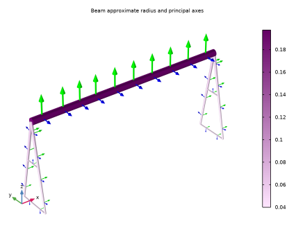
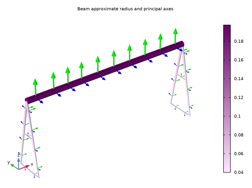
The supporting columns have box cross sections, varying from 100 mm-by-100 mm at the ground level to 200 mm-by-100 mm at the connection to the bridge. The wall thickness is 10 mm.
|
|
•
|
The horizontal crossbars between the columns have square box sections, 80 mm-by-80 mm with a wall thickness of 8 mm.
|
|
•
|
Bridge width: 12 m.
|
|
•
|
Crane height: 5 m.
|
|
•
|
Thermal load: The maximum temperature of the crane can rise to 50°C on a hot day. The stress-free assembly temperature is set to 20°C.
|
|
•
|
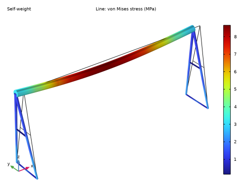
Self weight: In addition to the weight of the frame, the weight of the trolley carrying the payload (200 kg) is taken into account.
|
|
•
|
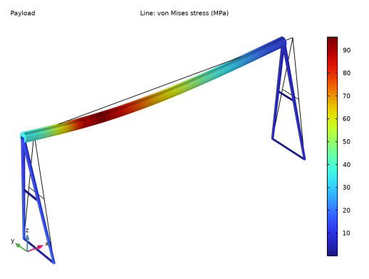
Payload: 15 ton are applied as a uniform load over a distance of 0.8 m of the bridge. This is the trolley width. The center of the trolley is placed at 3 m from the hinged end of the bridge.
|
|
1
|
|
2
|
|
3
|
Click Add.
|
|
4
|
Click
|
|
5
|
|
6
|
Click
|
|
1
|
|
2
|
|
3
|
|
4
|
Browse to the model’s Application Libraries folder and double-click the file portal_crane_parameters.txt.
|
|
1
|
|
2
|
|
4
|
Locate the Selections of Resulting Entities section. Find the Cumulative selection subsection. Click New.
|
|
5
|
|
6
|
Click OK.
|
|
7
|
|
1
|
|
2
|
On the object pol1, select Point 5 only.
|
|
3
|
|
4
|
|
5
|
On the object pol1, select Point 1 only.
|
|
6
|
Locate the Selections of Resulting Entities section. Find the Cumulative selection subsection. Click New.
|
|
7
|
|
8
|
Click OK.
|
|
1
|
|
2
|
On the object pol1, select Point 4 only.
|
|
3
|
|
4
|
|
5
|
On the object pol1, select Point 2 only.
|
|
6
|
Locate the Selections of Resulting Entities section. Find the Cumulative selection subsection. From the Contribute to list, choose Crossbars.
|
|
7
|
|
1
|
|
2
|
|
3
|
|
4
|
Click in the Graphics window and then press Ctrl+A to select all objects.
|
|
5
|
|
6
|
|
1
|
|
2
|
|
4
|
|
1
|
|
2
|
|
3
|
|
4
|
|
5
|
|
1
|
|
2
|
|
3
|
|
4
|
|
5
|
|
6
|
|
7
|
|
1
|
|
2
|
|
3
|
|
4
|
Specify the V vector as
|
|
1
|
|
2
|
|
3
|
|
4
|
|
5
|
|
6
|
|
7
|
|
8
|
|
9
|
|
1
|
In the Model Builder window, expand the Cross Section: Columns node, then click Section Orientation 1.
|
|
2
|
|
3
|
|
4
|
Specify the V vector as
|
|
1
|
|
2
|
In the Settings window for Cross-Section Data, type Cross Section: Crossbars in the Label text field.
|
|
3
|
|
4
|
|
5
|
|
6
|
|
7
|
|
8
|
|
9
|
|
1
|
In the Model Builder window, expand the Cross Section: Crossbars node, then click Section Orientation 1.
|
|
2
|
|
3
|
|
4
|
Specify the V vector as
|
|
1
|
|
1
|
|
3
|
In the Settings window for Prescribed Displacement/Rotation, locate the Prescribed Displacement section.
|
|
4
|
|
5
|
|
1
|
|
3
|
|
4
|
|
1
|
|
1
|
|
2
|
|
1
|
In the Model Builder window, under Global Definitions>Load and Constraint Groups click Load Group 1.
|
|
2
|
|
3
|
|
1
|
|
2
|
|
4
|
|
5
|
|
6
|
|
7
|
|
8
|
Click OK.
|
|
9
|
|
1
|
|
2
|
|
3
|
|
4
|
|
5
|
|
6
|
|
1
|
In the Model Builder window, under Global Definitions>Load and Constraint Groups click Load Group 2.
|
|
2
|
|
3
|
|
1
|
|
2
|
|
3
|
|
1
|
|
2
|
|
3
|
Find the Expression for remaining selection subsection. In the Temperature text field, type maxTemp.
|
|
1
|
In the Model Builder window, under Component 1 (comp1)>Beam (beam)>Linear Elastic Material 1 click Thermal Expansion 1.
|
|
2
|
|
1
|
In the Model Builder window, under Global Definitions>Load and Constraint Groups click Load Group 3.
|
|
2
|
|
3
|
|
1
|
|
2
|
|
3
|
|
4
|
Click
|
|
6
|
Click
|
|
8
|
Click
|
|
10
|
|
1
|
|
2
|
|
3
|
|
4
|
|
5
|
|
6
|
|
7
|
|
8
|
|
1
|
|
2
|
|
3
|
|
4
|
|
1
|
|
2
|